
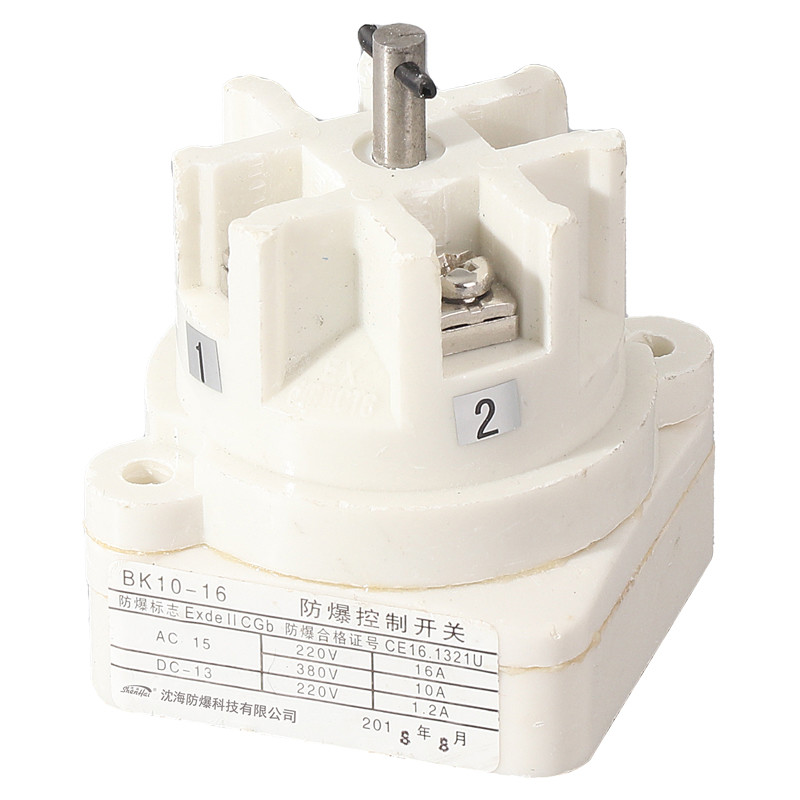
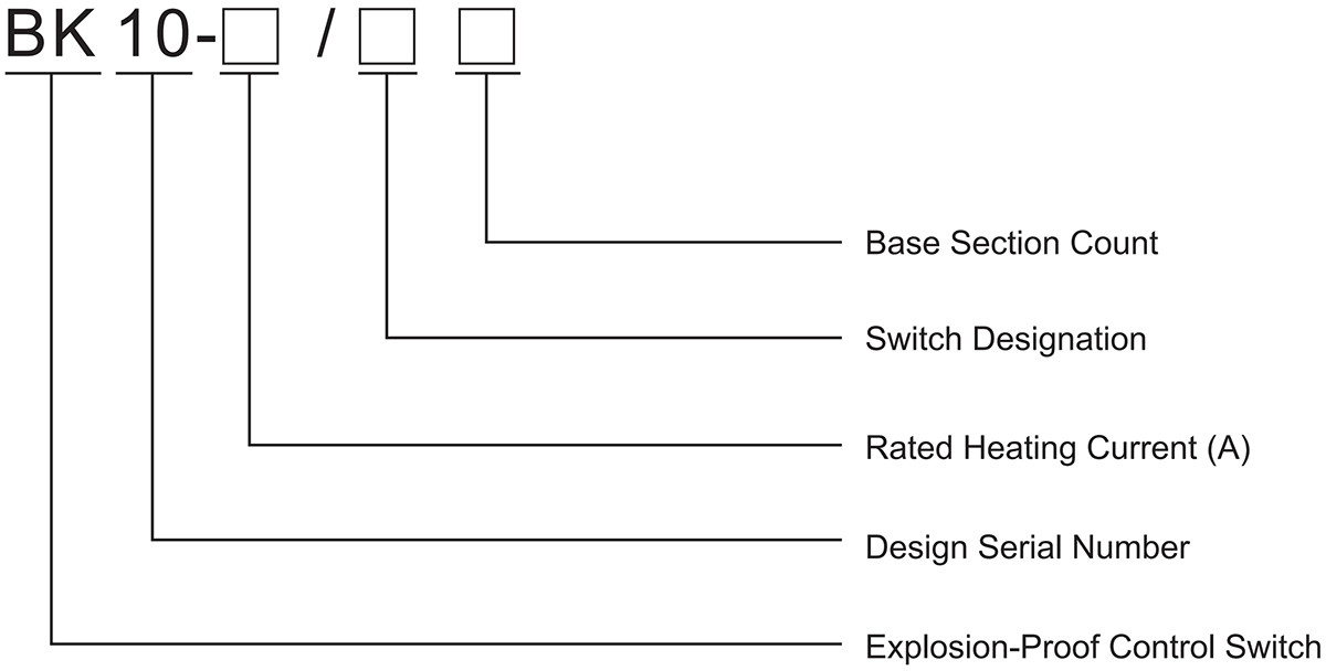
Model Meaning
Implementation Standard
GB/T3836.1、GB/T3836.2、GB/T3836.3、IEC60079-0、IEC 60079-1、IEC 60079-7、EN60079-0、EN60079-1、EN60079-7
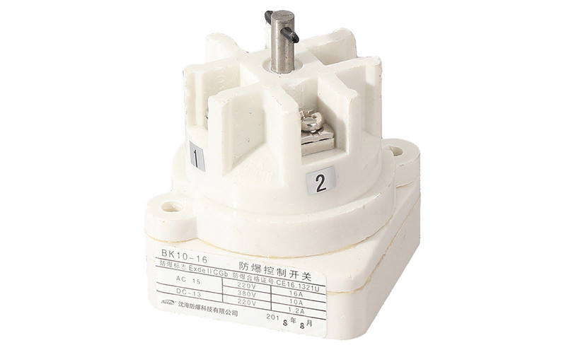
Technical Parameter
| Explosion-Proof Marking | Rated Voltage | Rated Current |
|---|---|---|
| Ex db eb IIC T6 Gb | AC 380V, AC 220V | 16A |
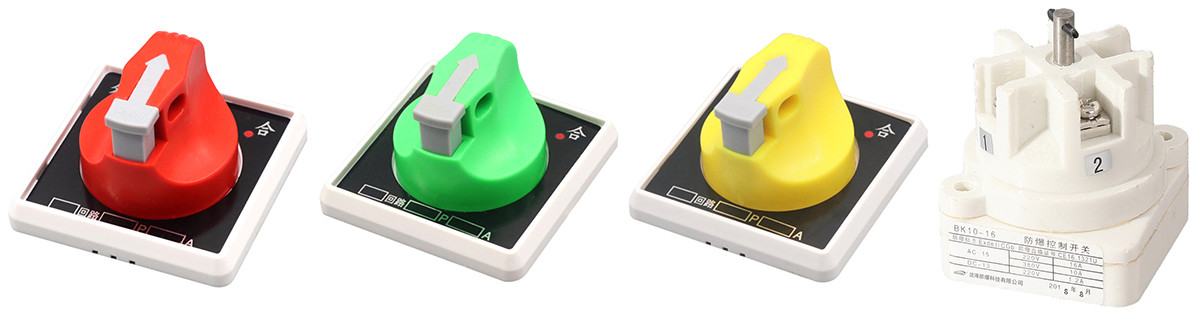
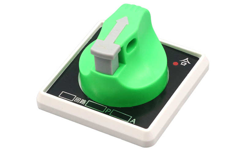
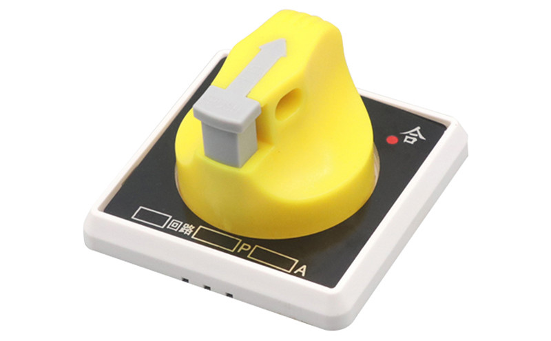
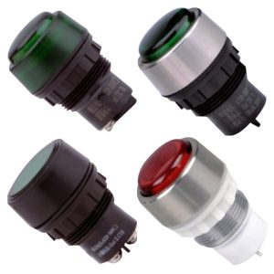
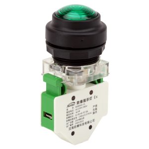
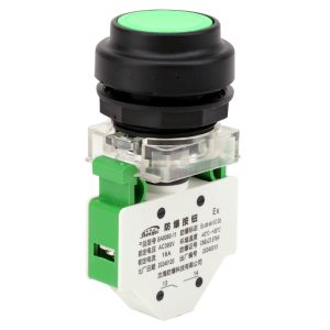
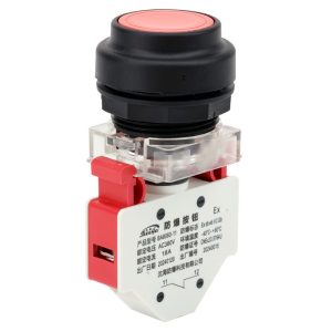
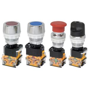
Product Features
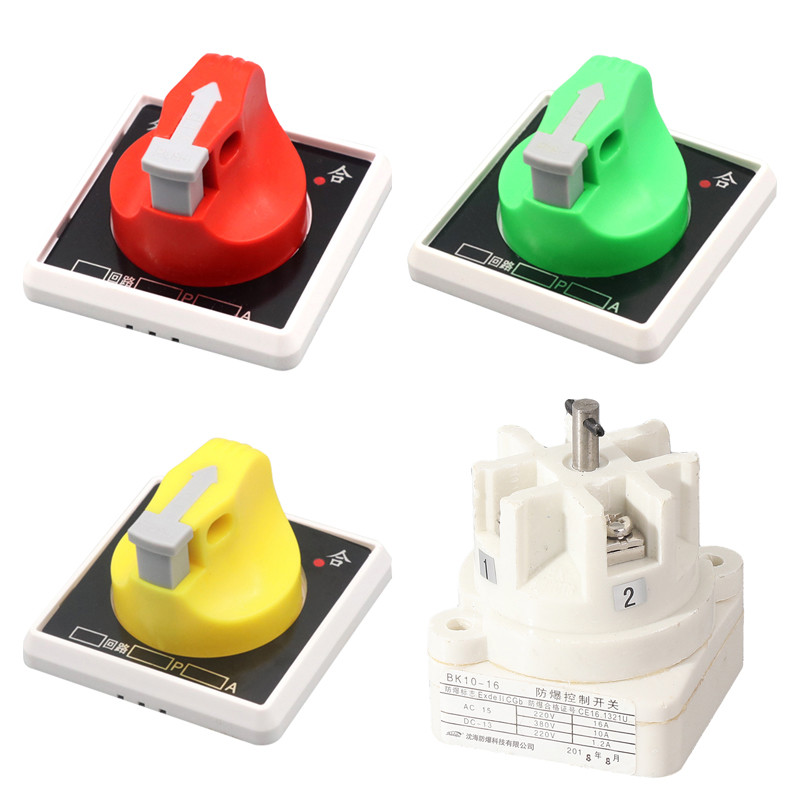
1. The housing is injection molded from premium imported engineering plastic or stainless steel;
2. This device cannot be used independently in explosive environments;
3. This device is primarily designed for use with all our enhanced safety or explosion-proof corrosion-resistant enclosures;
4. This device can also be used with our flameproof products.
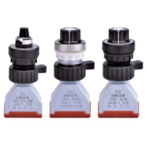
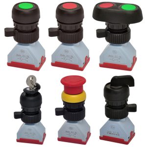
Switch Designation
| Switch Designation | Panel Knob Position (Solid lines indicate fixed position; dashed lines indicate self-resetting) | Equivalent Circuit | Contact Diagram | Functional Description |
|---|---|---|---|---|
| A | 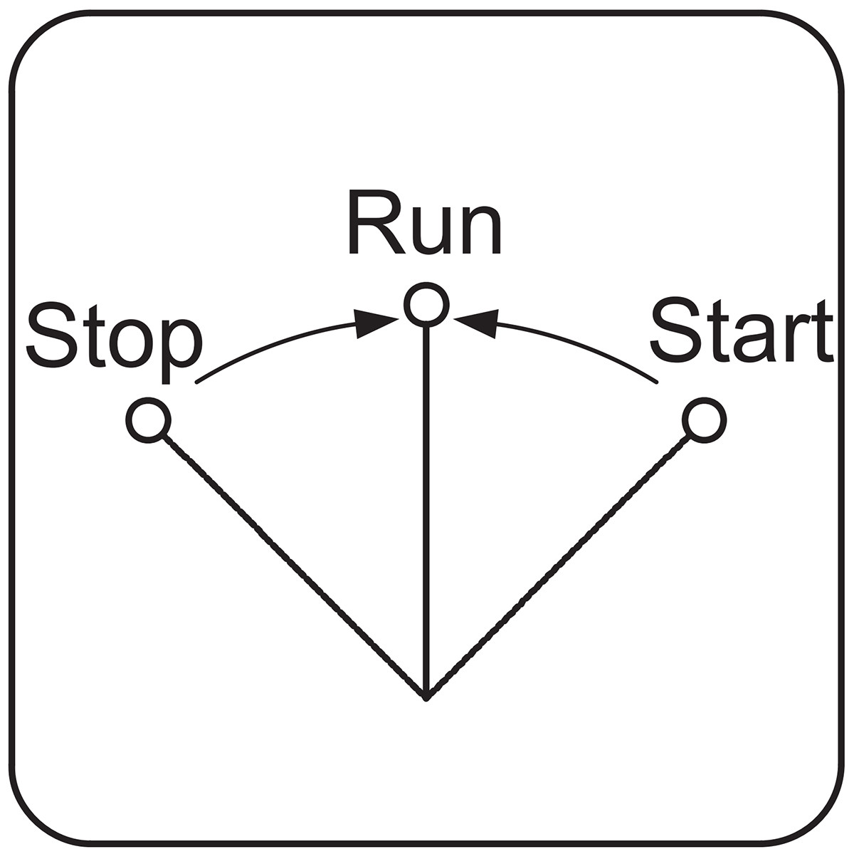 | 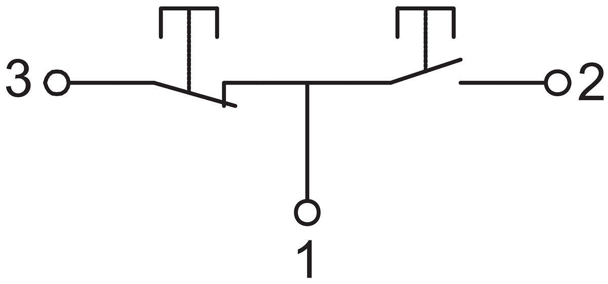 | 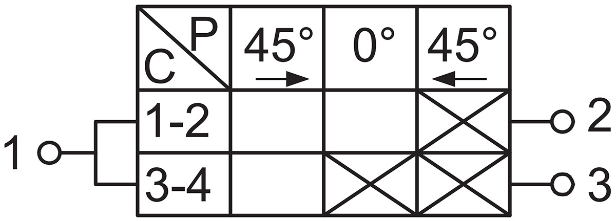 | Function wiring is identical to dual-control buttons, with automatic reset. |
| B | 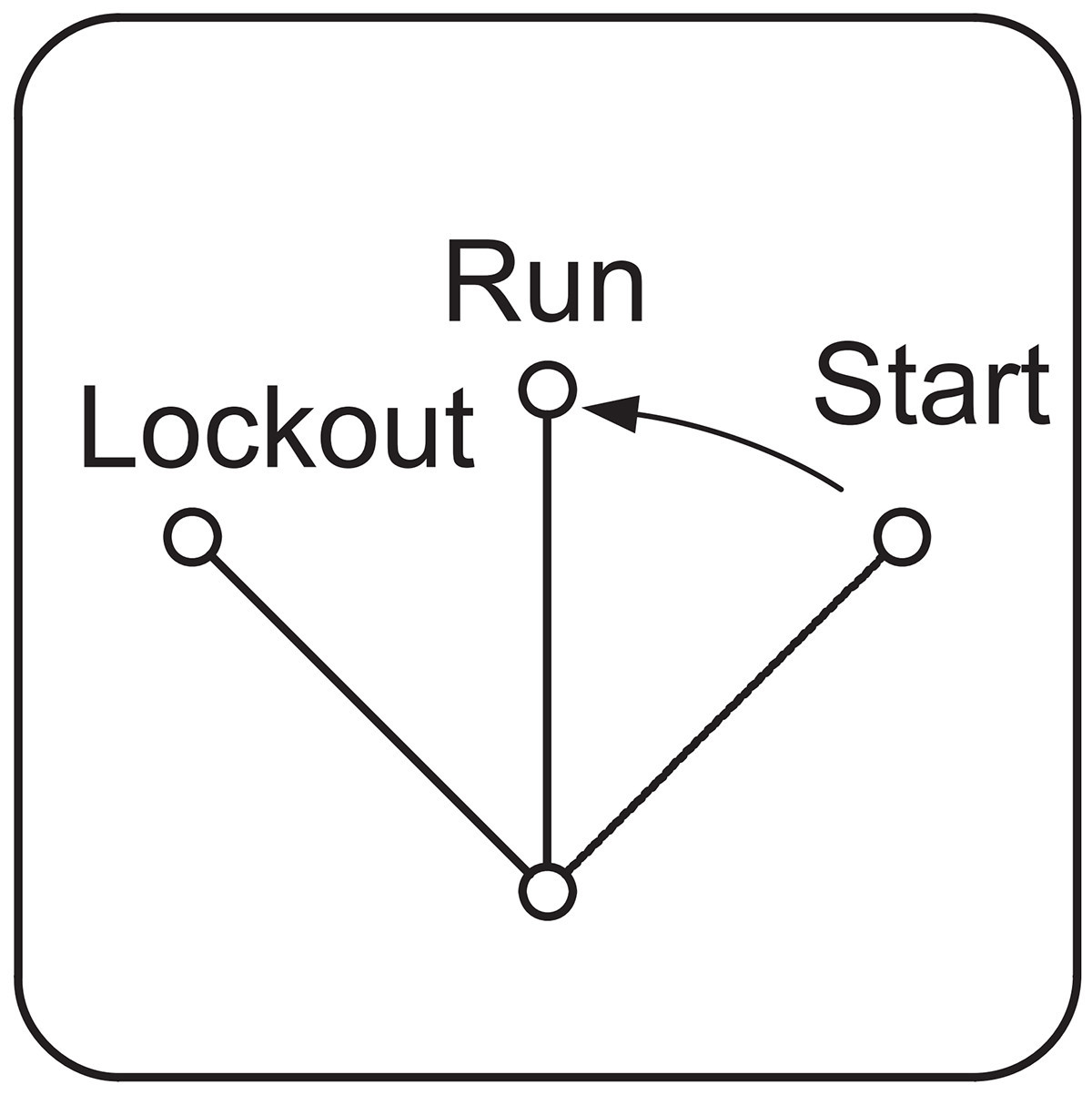 | 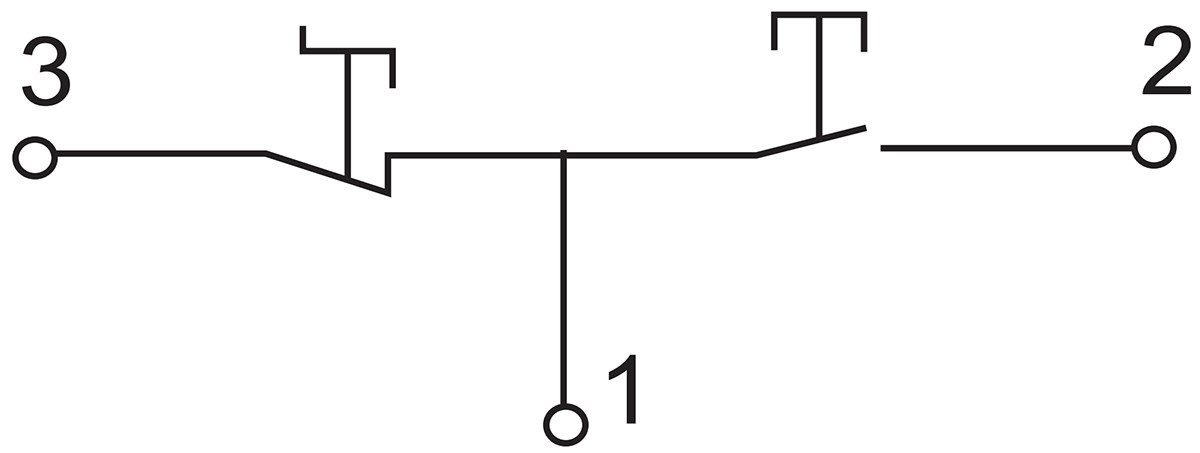 | 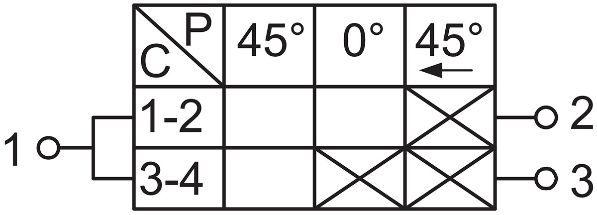 | A “Lock-Stop” position has been added. This position forces the normally closed button open, thereby preventing field operations from being controlled by the control room and reducing the risk of accidents. |
| C | | 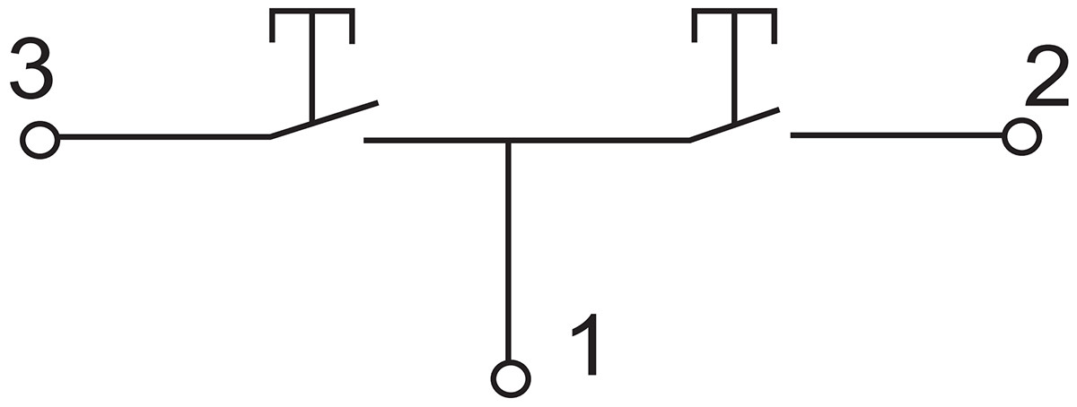 | 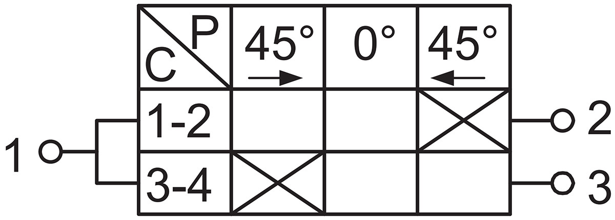 | A pushbutton with two normally open contacts, featuring automatic reset, suitable for high-voltage motor control circuits. |
| D |  | 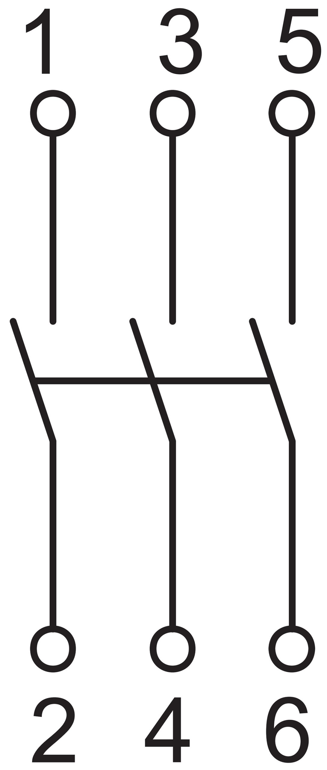 | 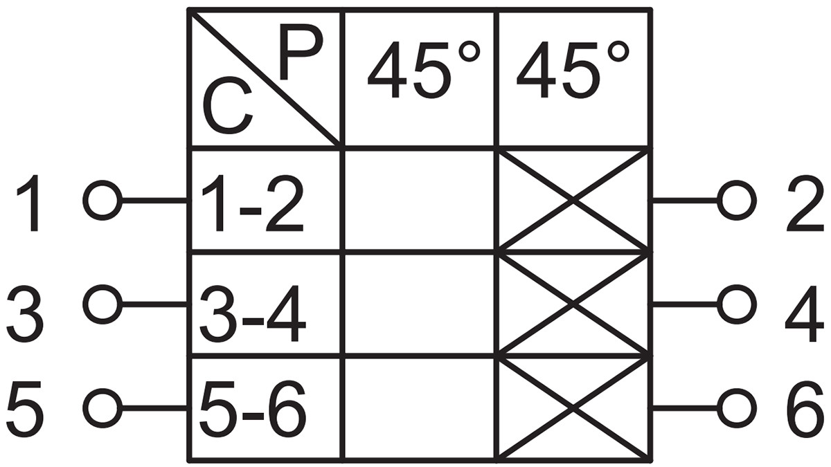 | For low-power switching applications, such as small axial fans, water pumps, etc. |
| E | 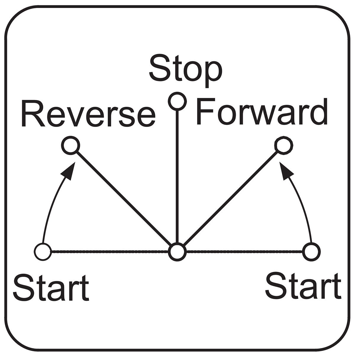 | 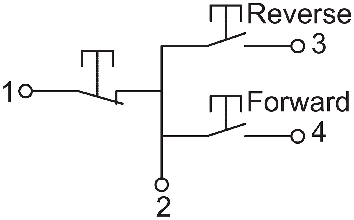 | 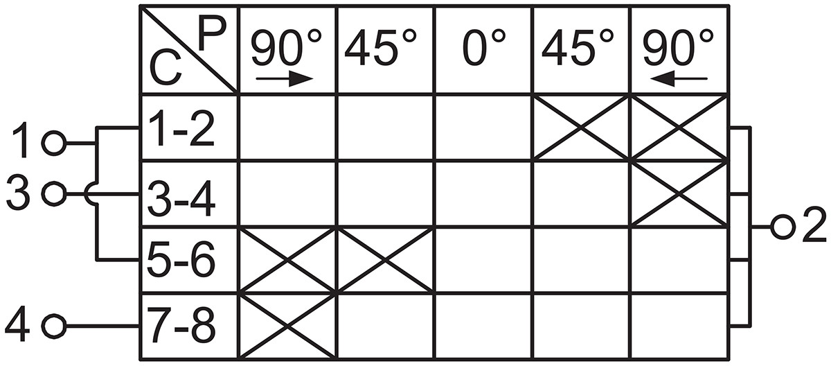 | Functionality and wiring are identical to the three-button configuration. Forward and reverse buttons automatically reset. After stopping and positioning, the “lock-out” function engages. The lock-out is released after operational movement. This switch prevents simultaneous engagement of forward and reverse starters. It is also suitable for star-delta starting circuits. |
| F | 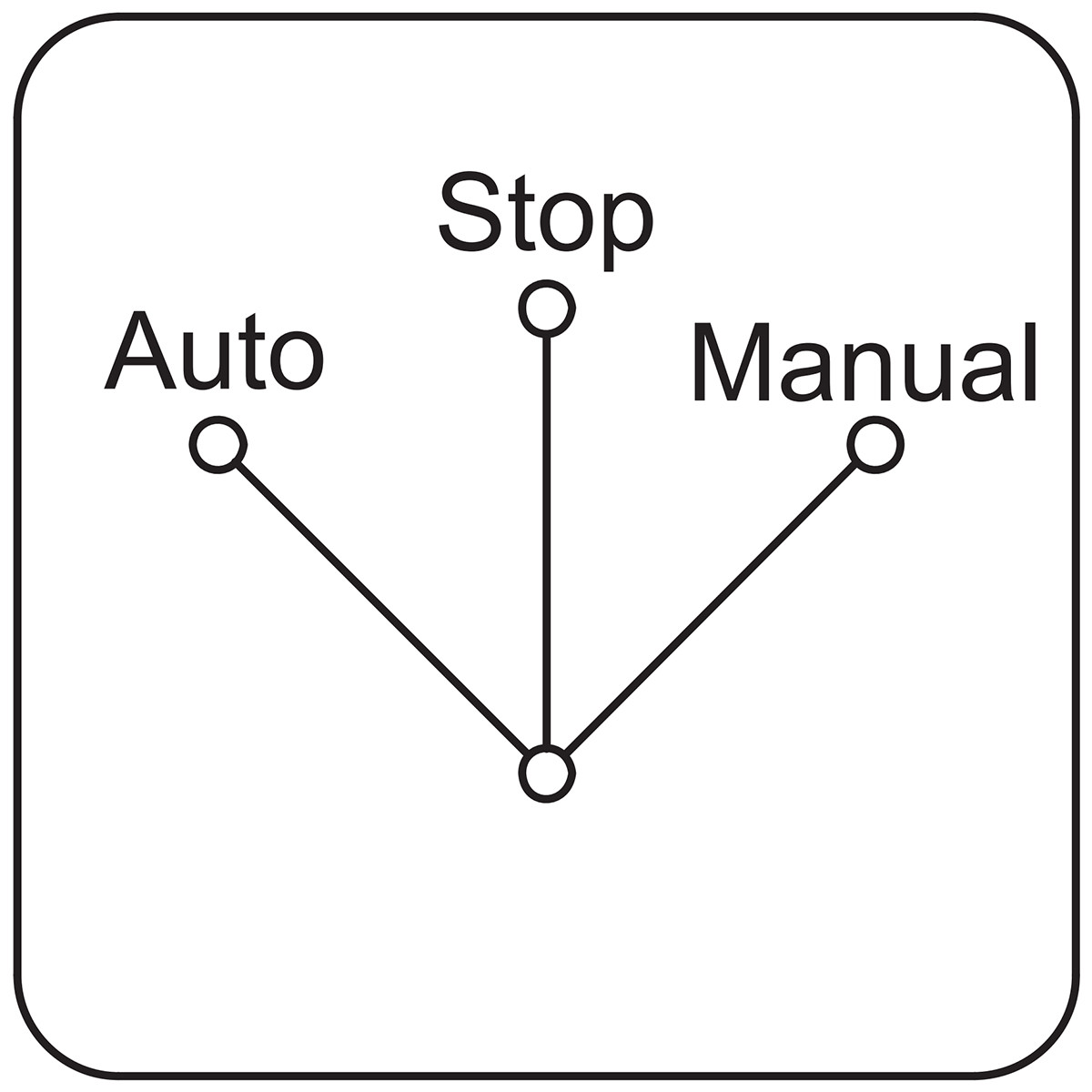 | 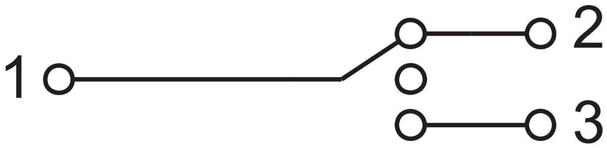 | 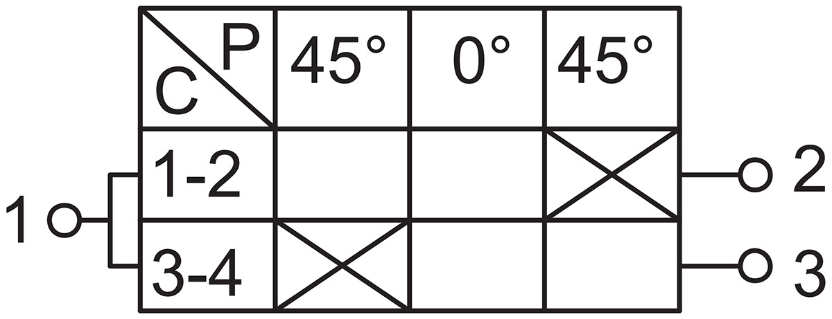 | Selector switch with a stop position in the middle. |
| G | 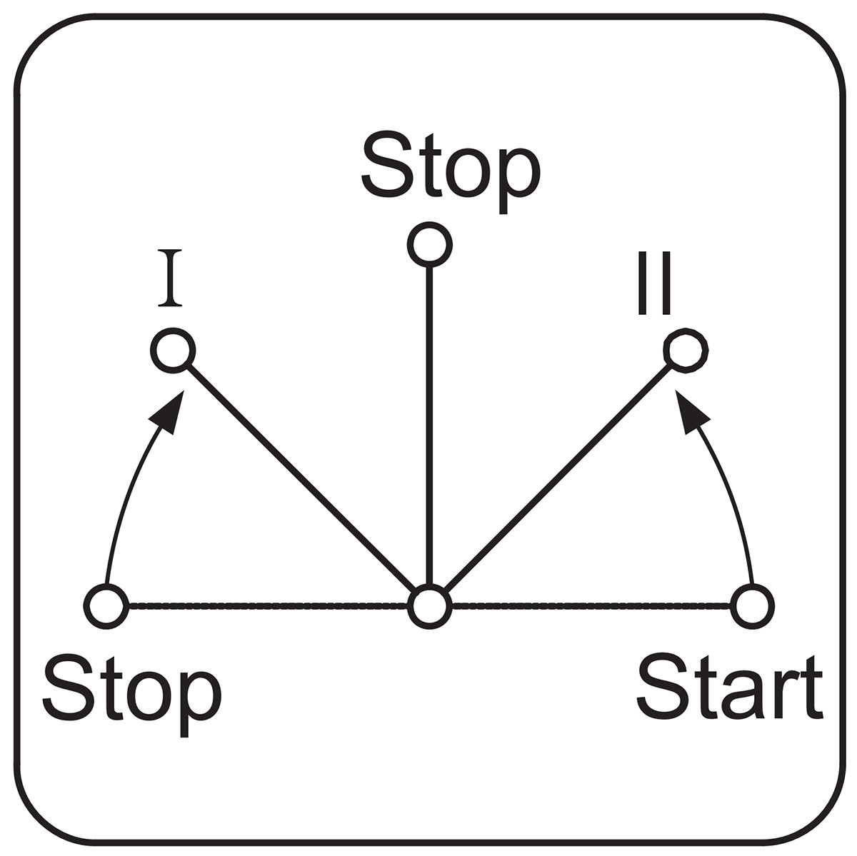 | 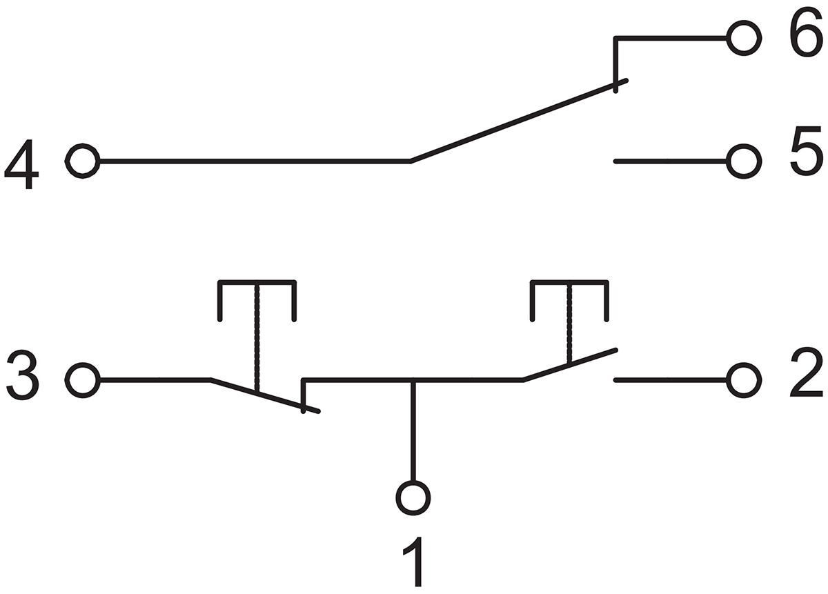 | 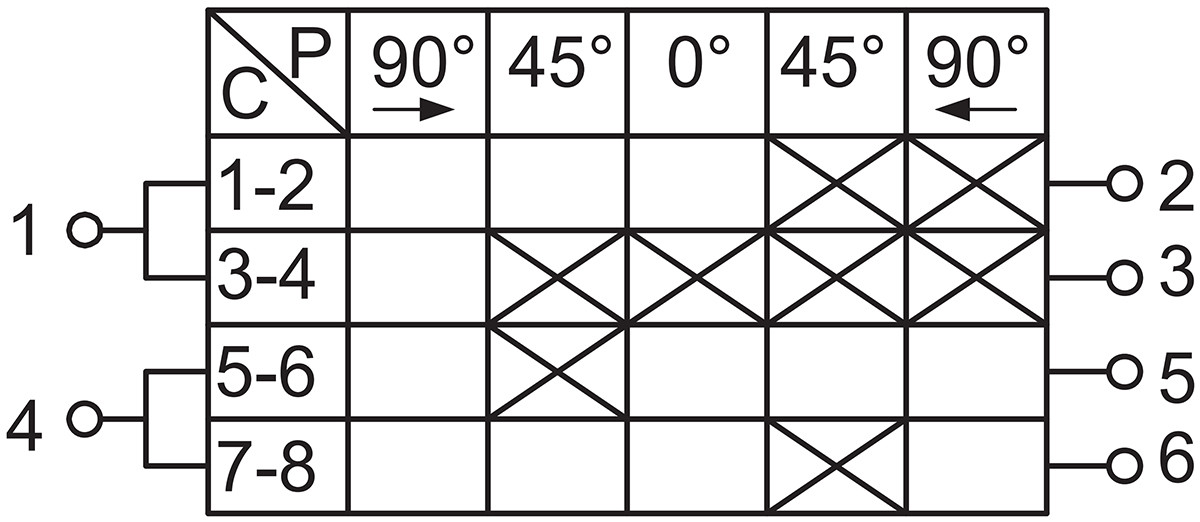 | Equivalent to two buttons and a toggle switch mounted on a single shaft, capable of outputting liaison signals or monitoring signals both before and after starting and stopping. |
| H | 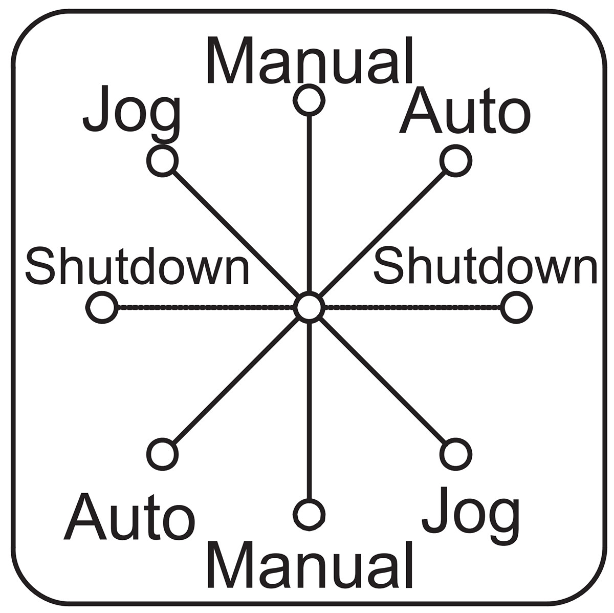 | 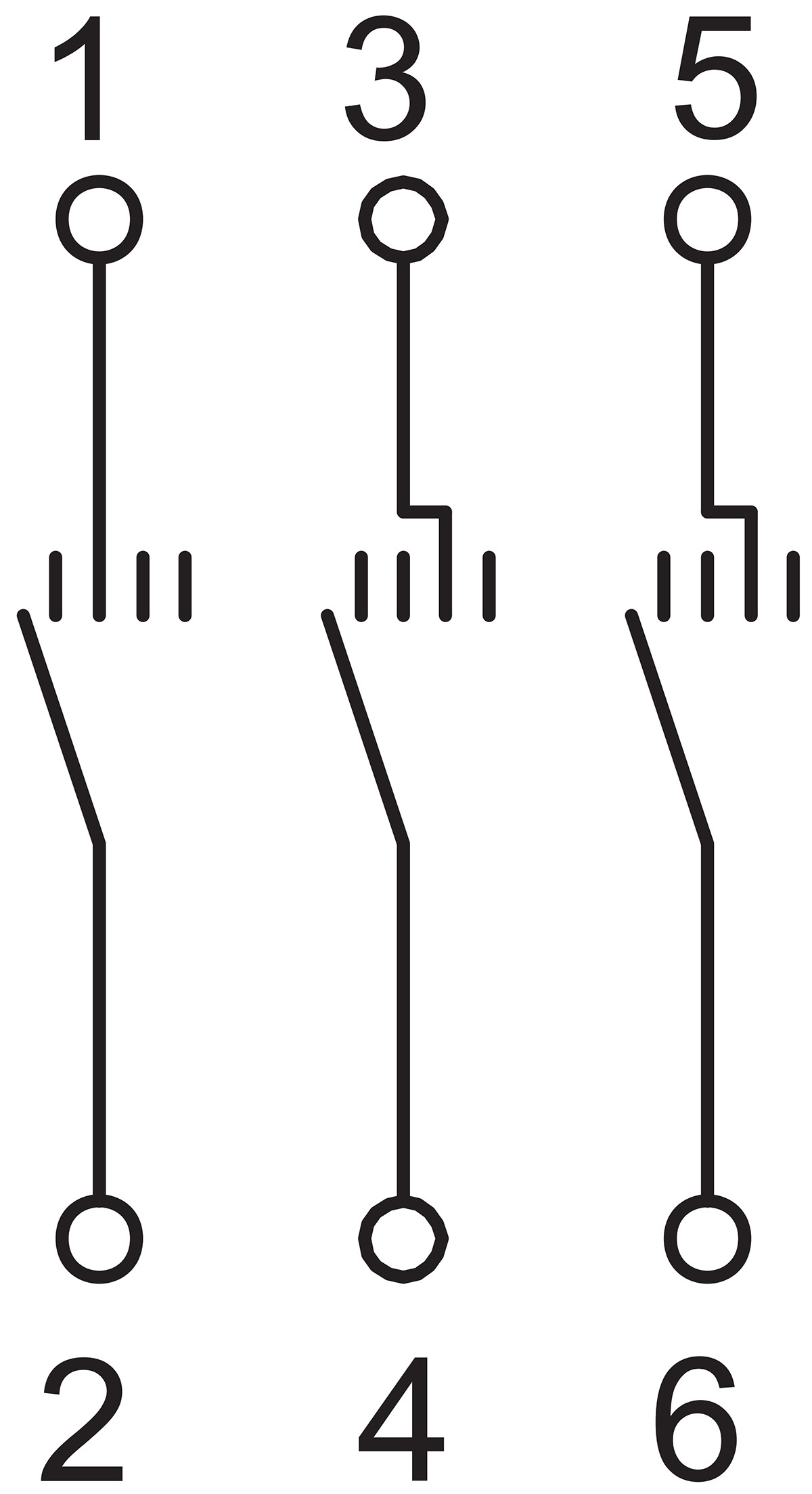 | 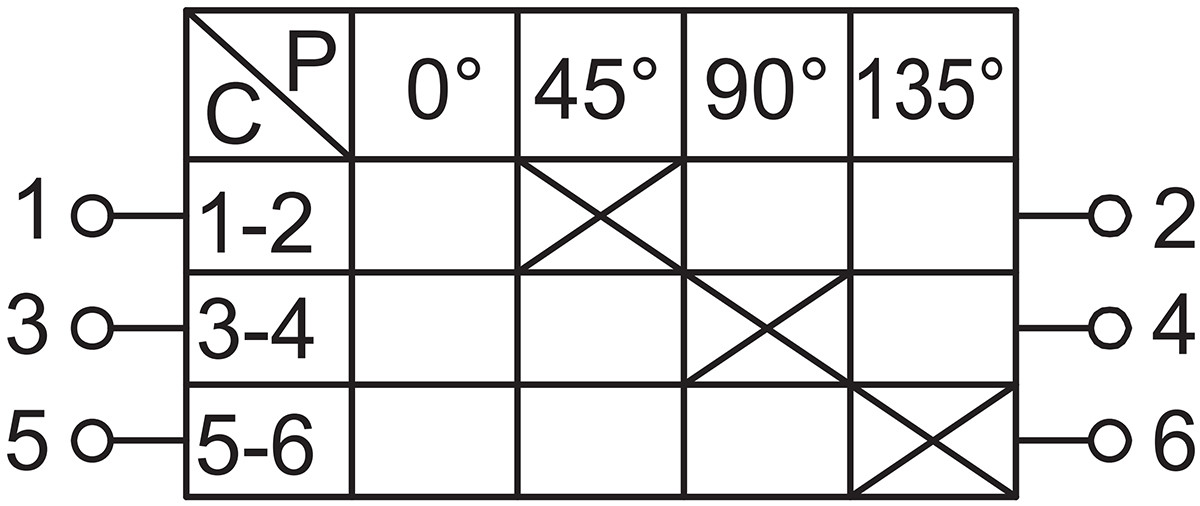 | Rotation direction is arbitrary, with multiple signals transmitted step by step. |
| I | | 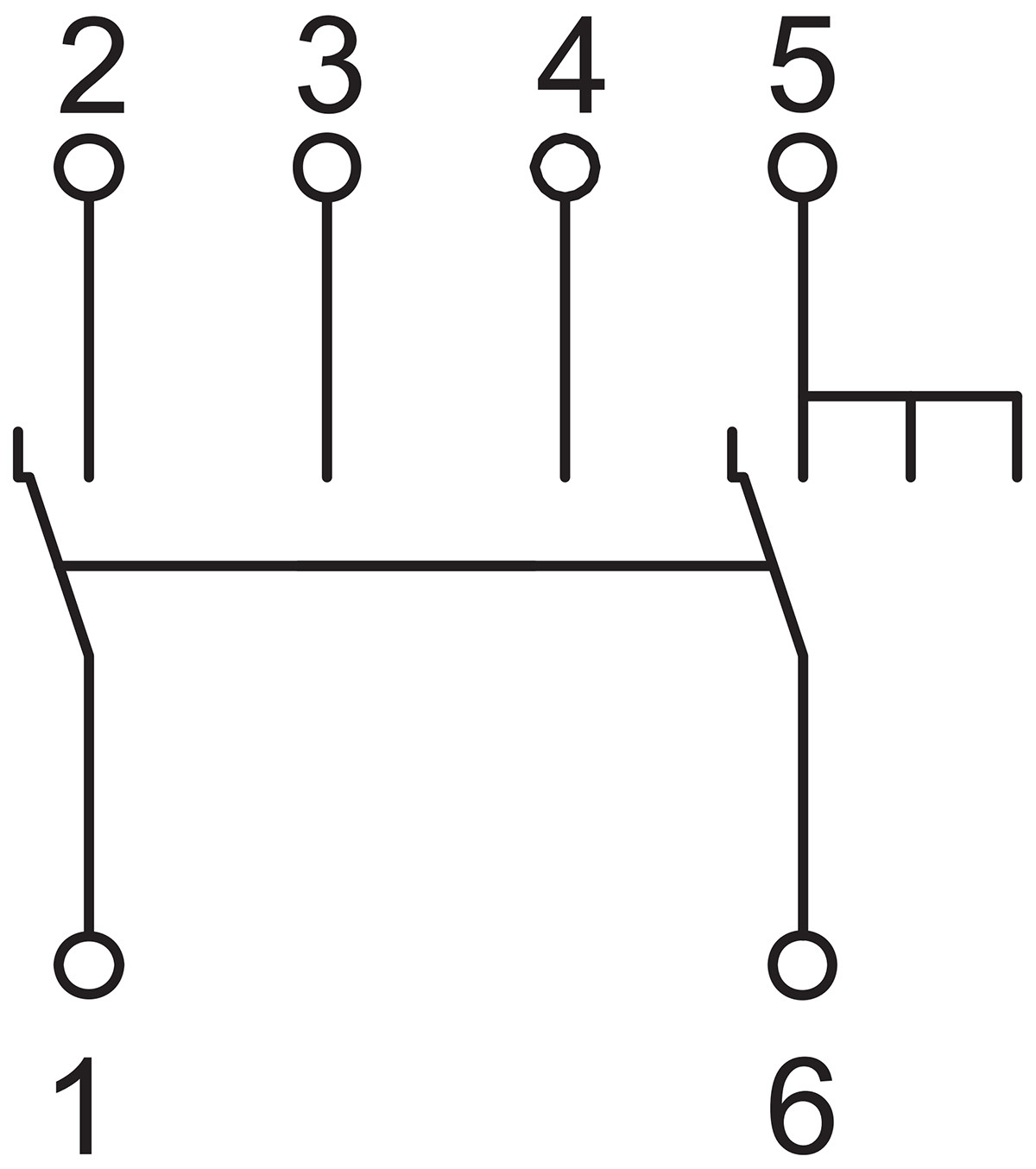 | 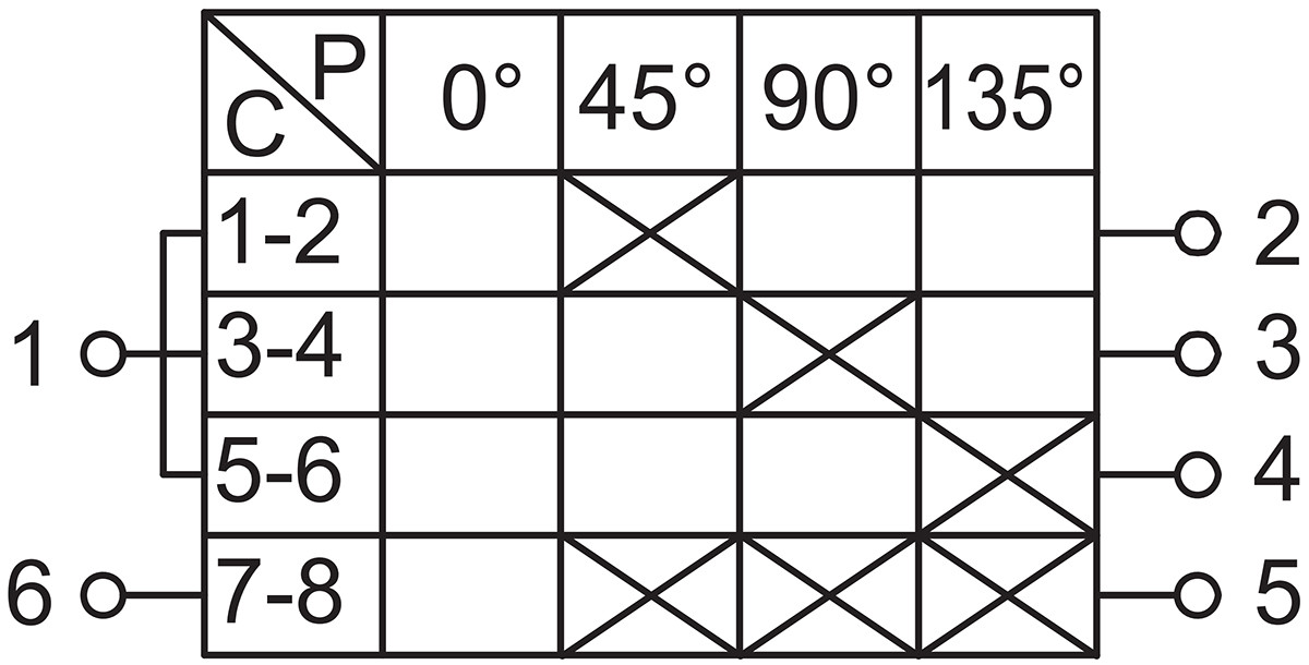 | Add total signal transmission functionality to the H platform. |
| J | 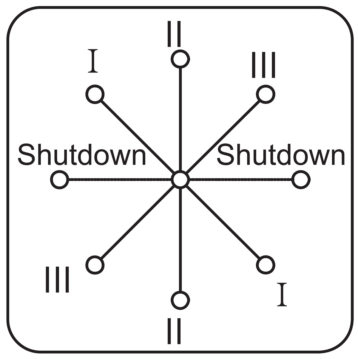 | 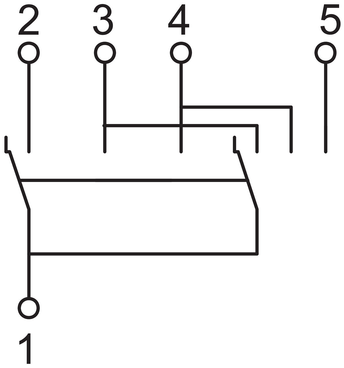 | 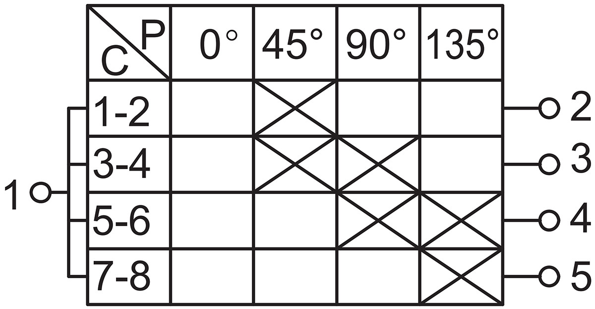 | Binary encoding, step-by-step switching. |
| K | 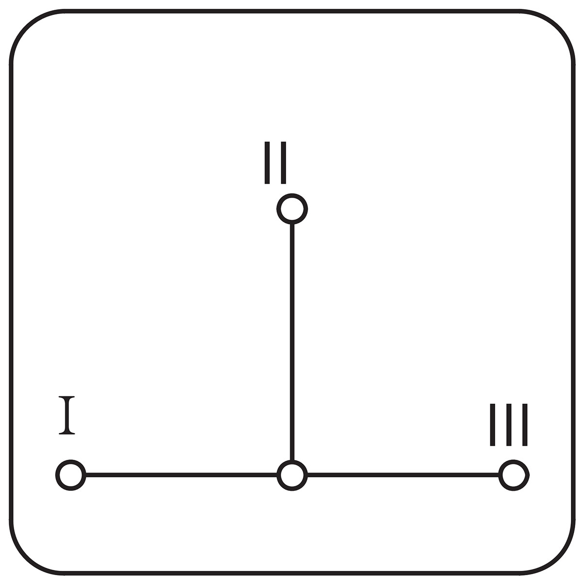 |  | 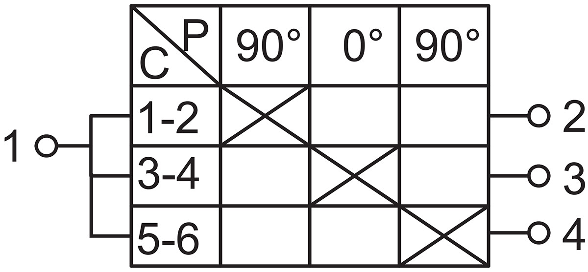 | Toggle switch |
| L | 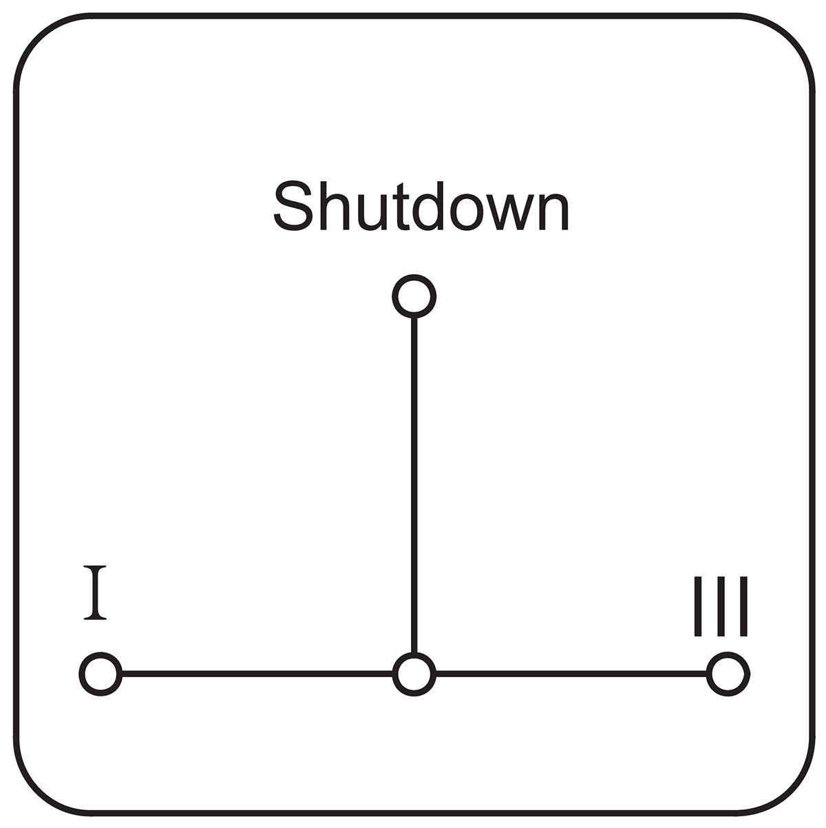 |  | 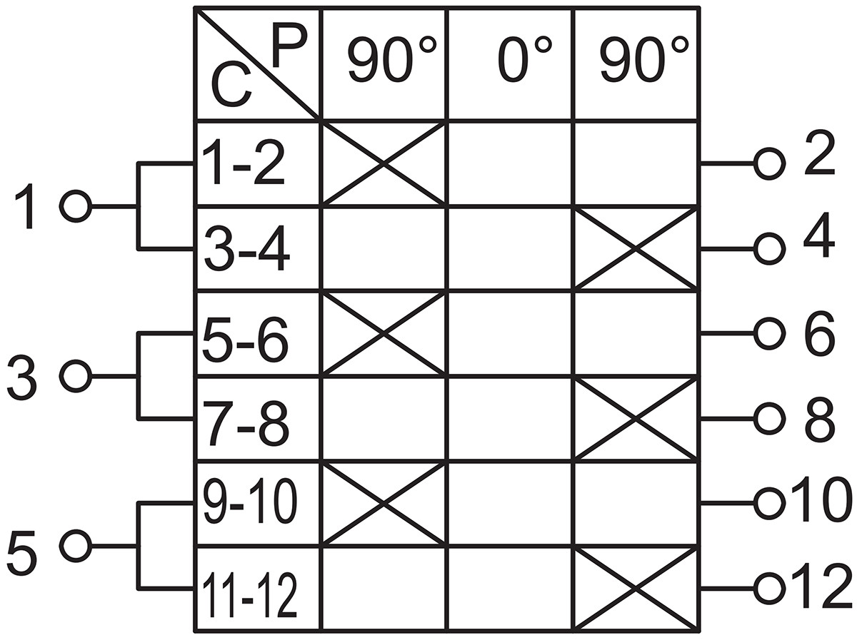 | Toggle switch |
| M | 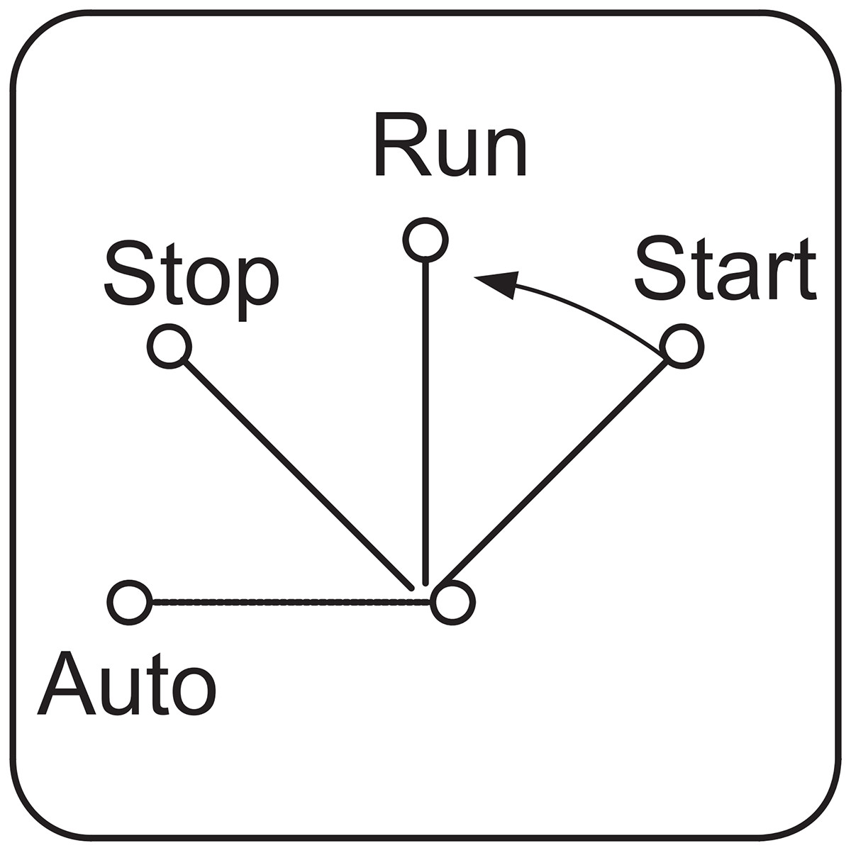 |  | 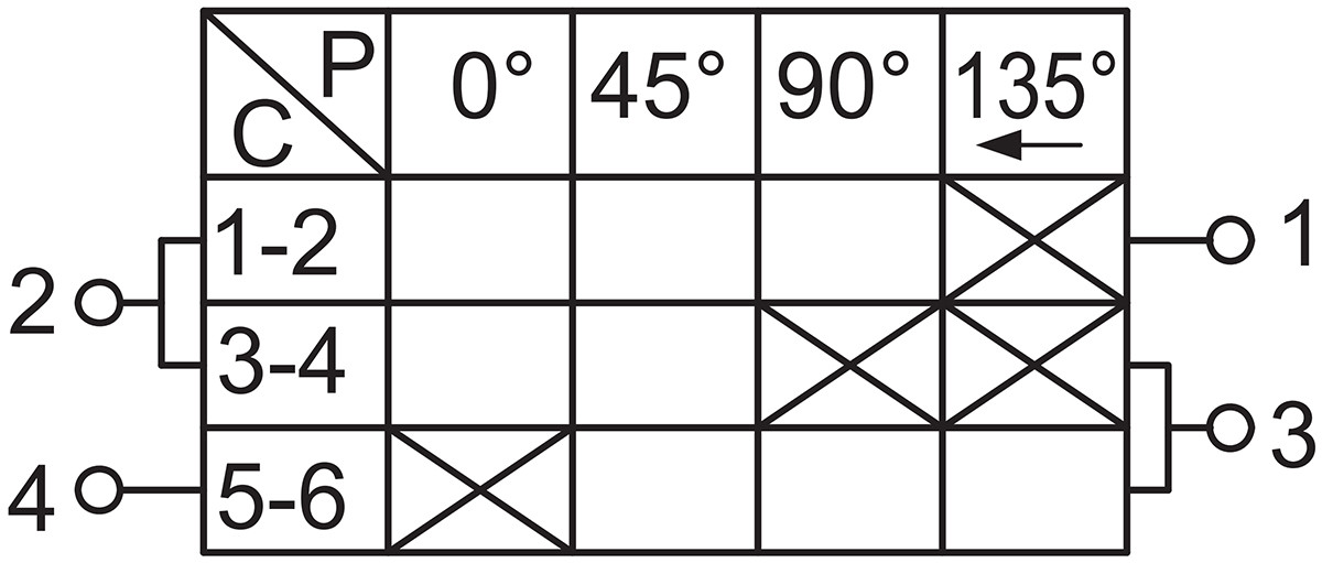 | Three-position switch for automatic, manual, and start modes. Start reset required. After starting, must pass through the stop position before shifting to the stop position, then to the automatic position. |
| N | 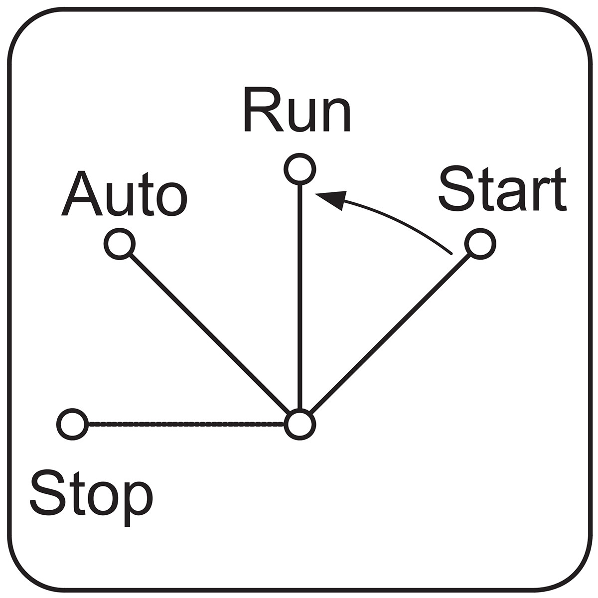 | 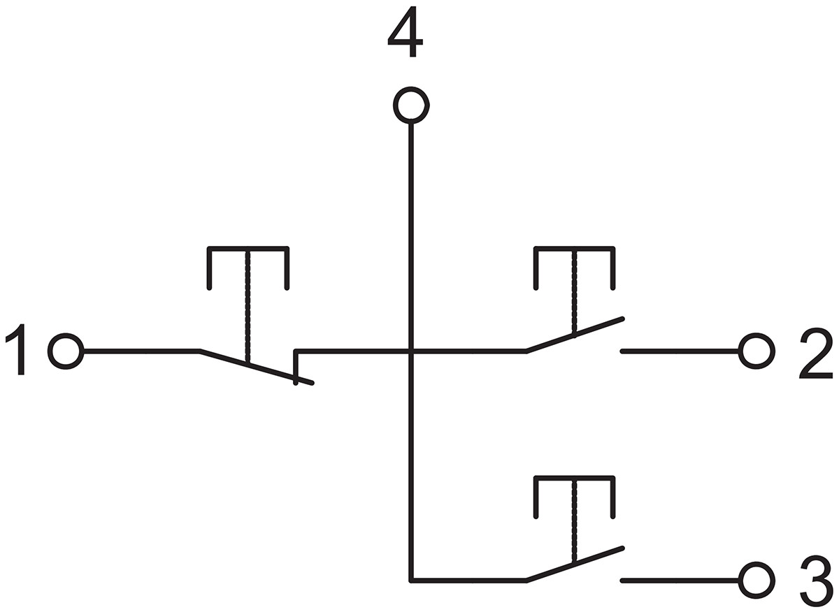 | 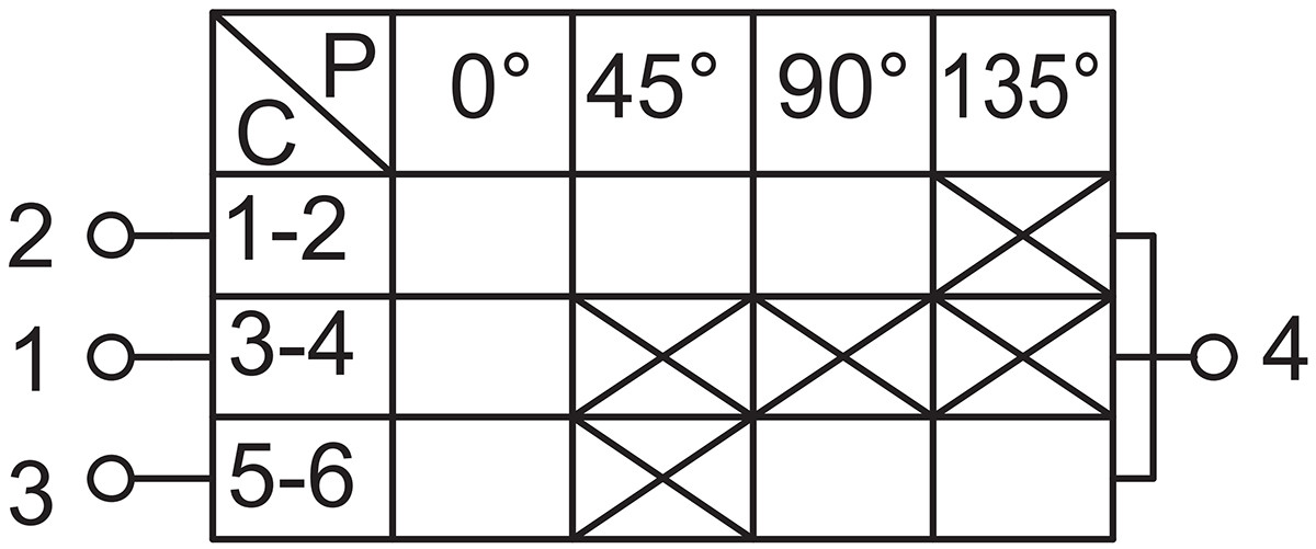 | Unlike the M-type switch, it automatically switches to rotation without stopping after manual activation. |
| O | | 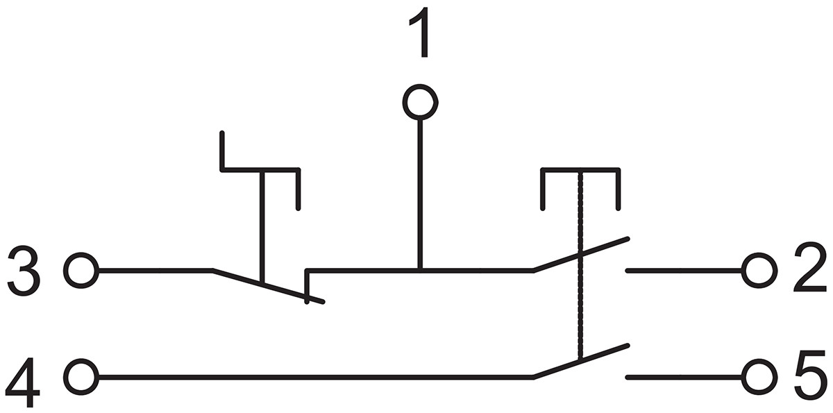 | 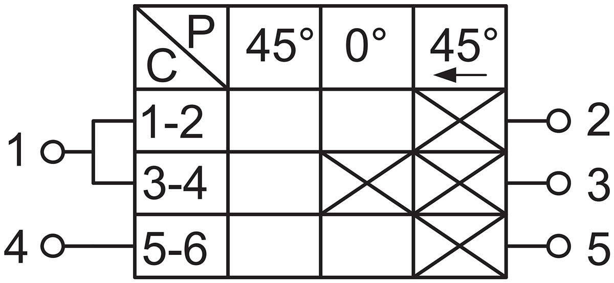 | The starter features dual contacts with a “lock-out” function and self-resetting upon startup. |
| P | | 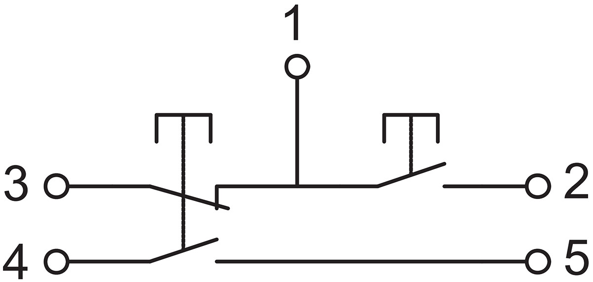 | 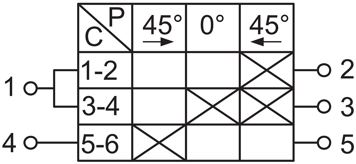 | The stop contact is double-pole and can also replace either A or C individually. |
| Q | | 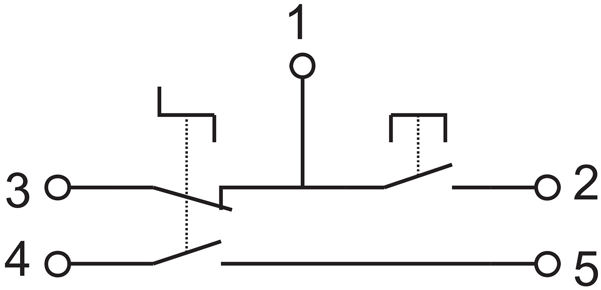 | 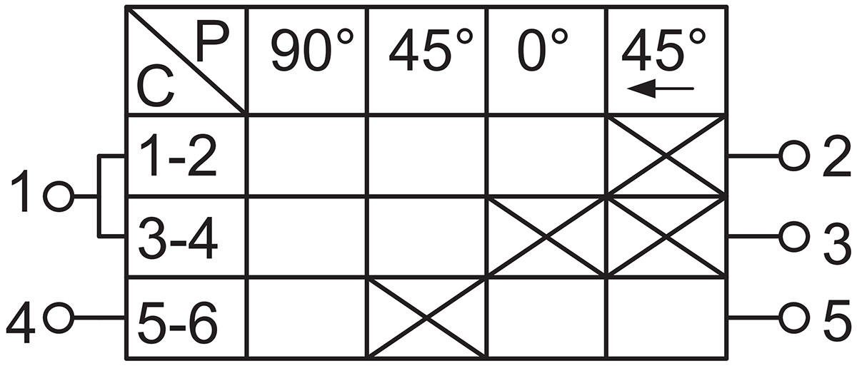 | Stop with dual contacts engaged, lock-off position for starting, automatic reset. |
| R | | 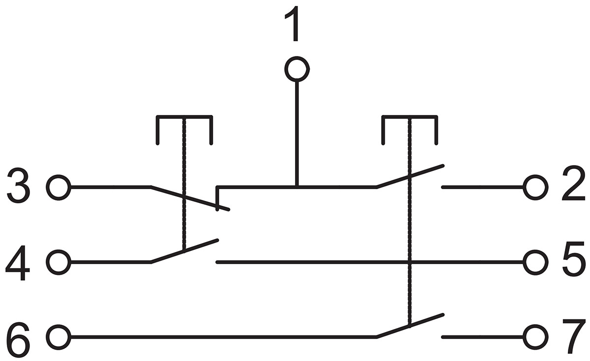 | 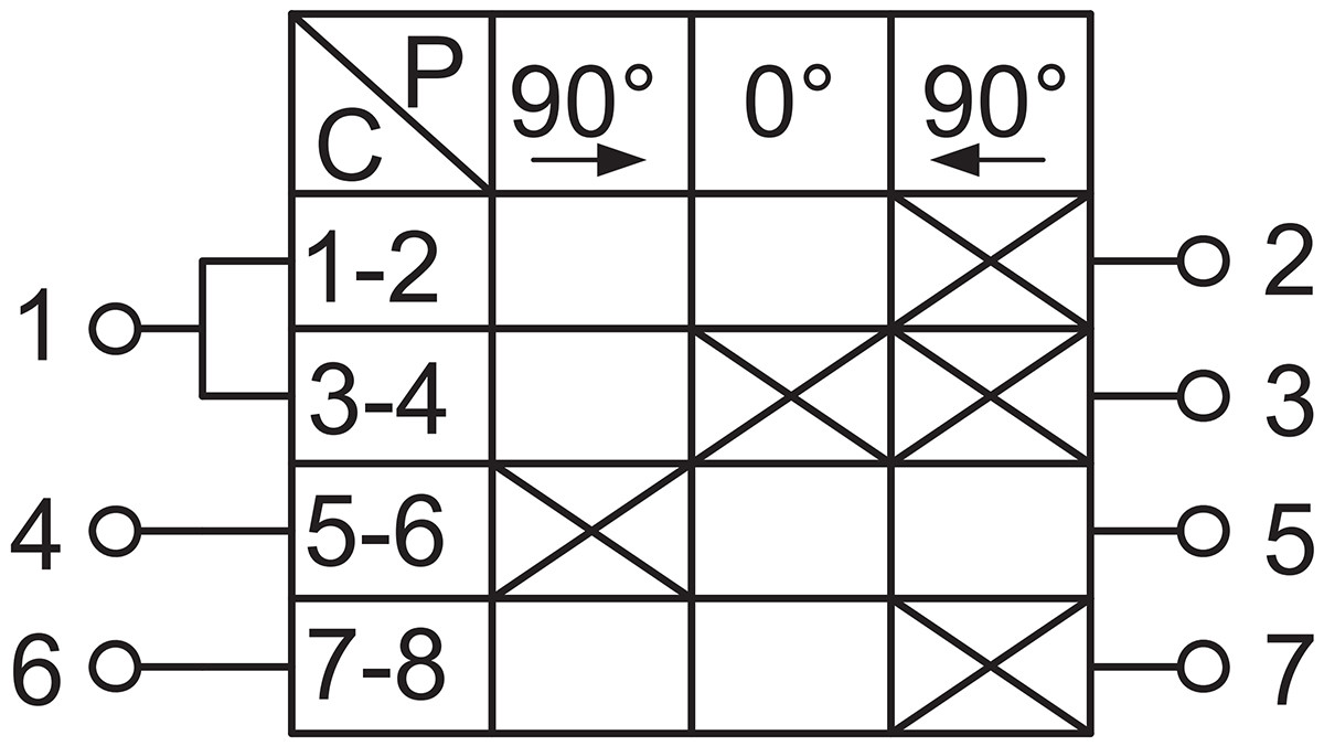 | The contact signal circuit closes from an open state to the signal position, and disconnects in other states after the start reset. This ensures the signal switch operates unidirectionally. It is suitable for control circuits requiring communication requests before startup. |
| S | 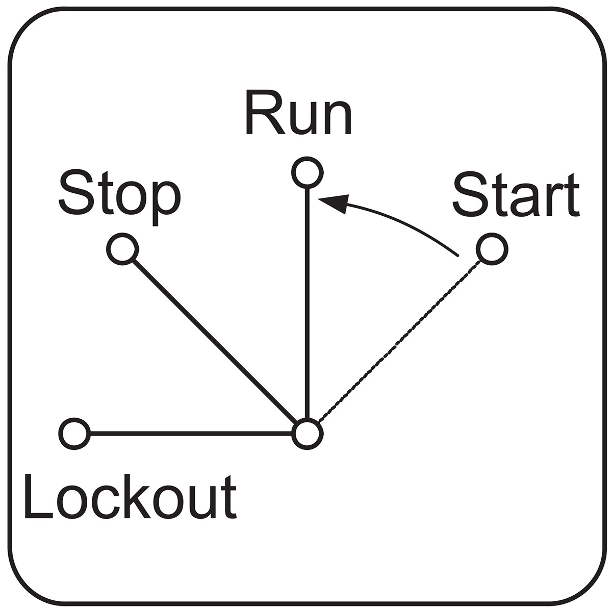 | 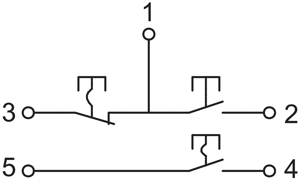 |  | Both start and stop functions include a lock-out feature to prevent accidental operation and cannot automatically reset. |
| T | 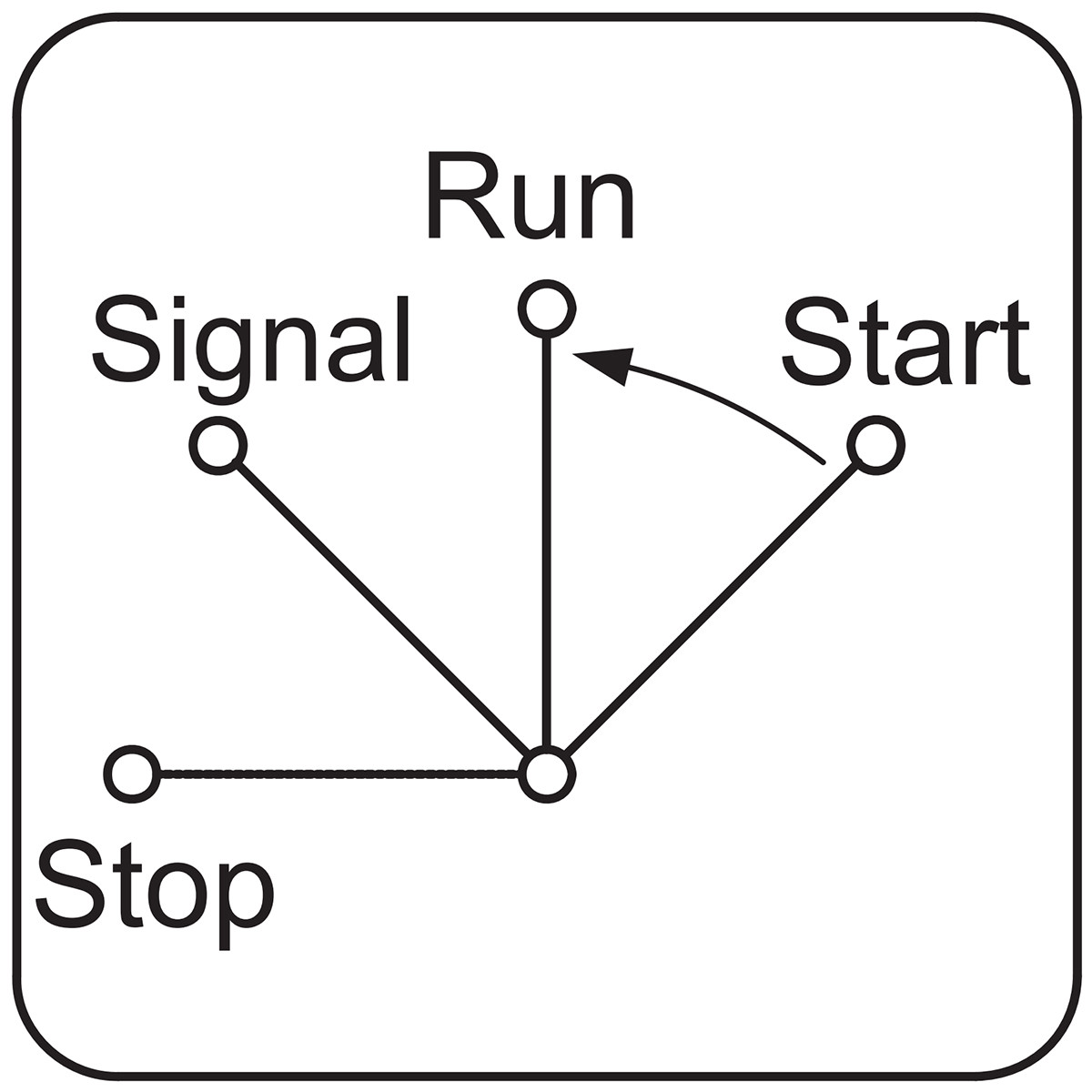 | 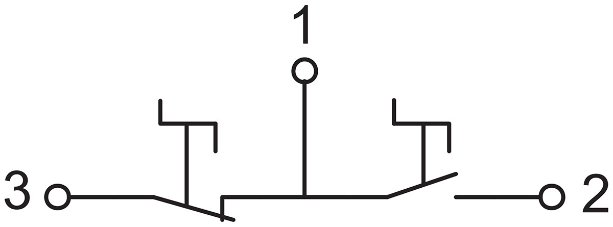 | 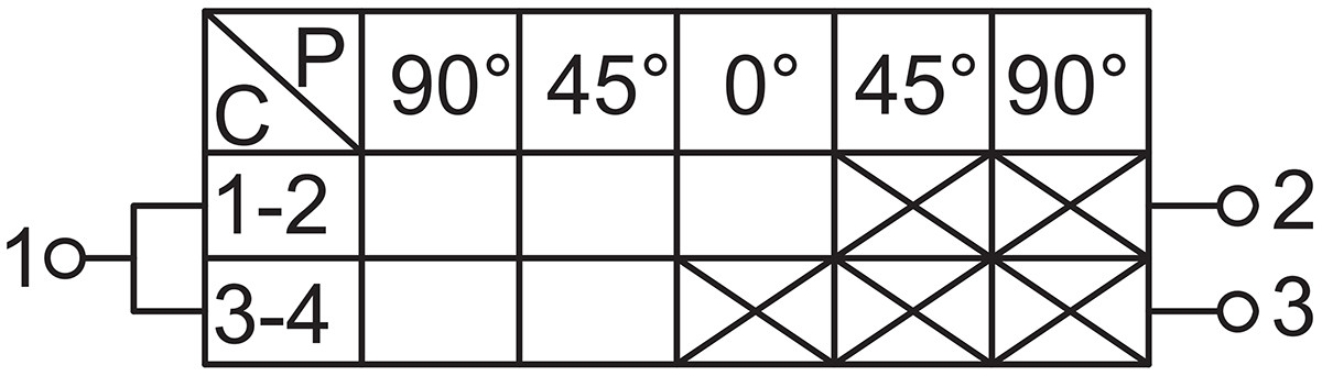 | Dual-Control Selector Switch |
| U | 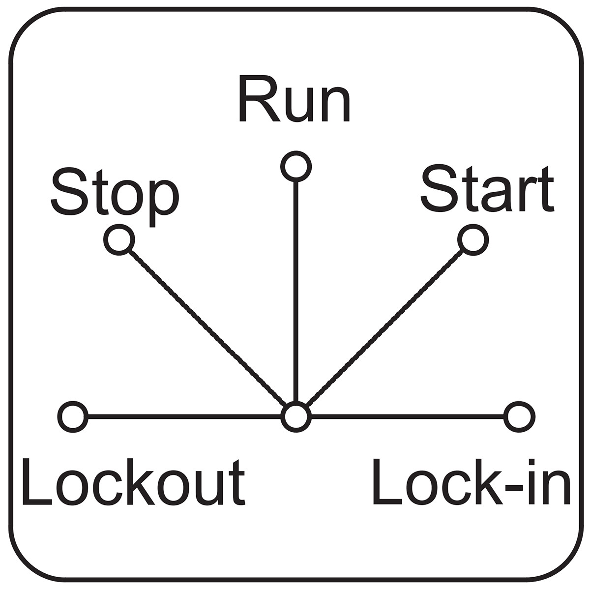 | 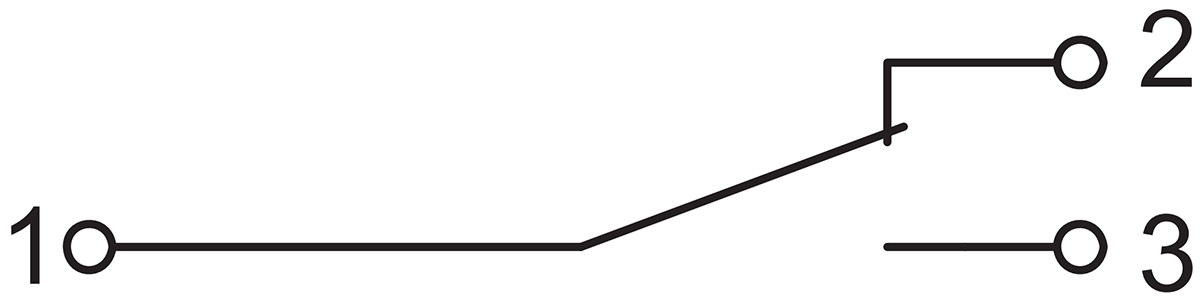 | 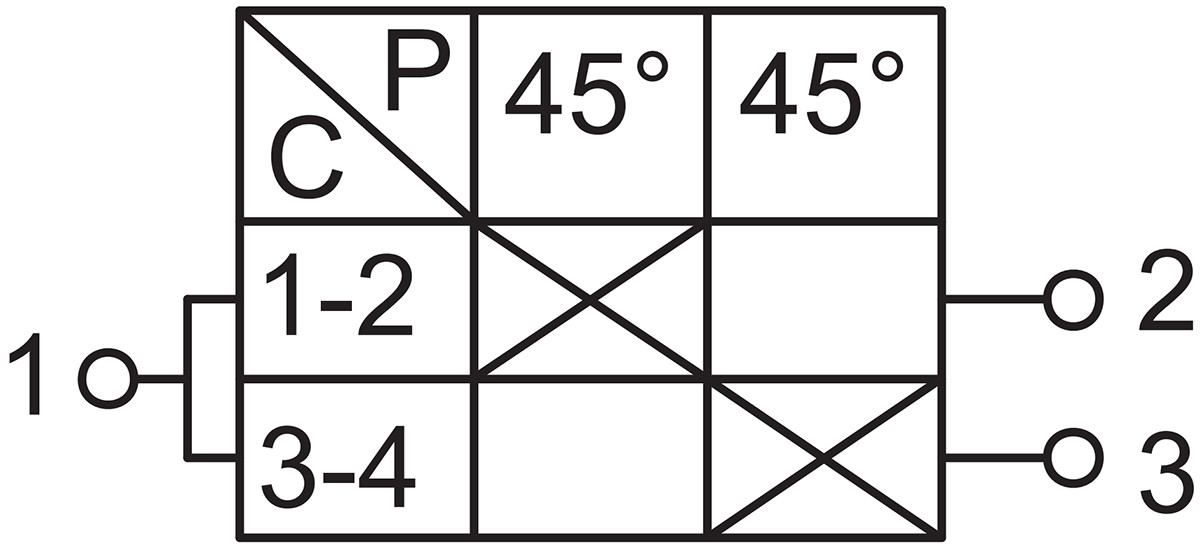 | Voltage Phase-Shifting Measurement Switch |
| V | 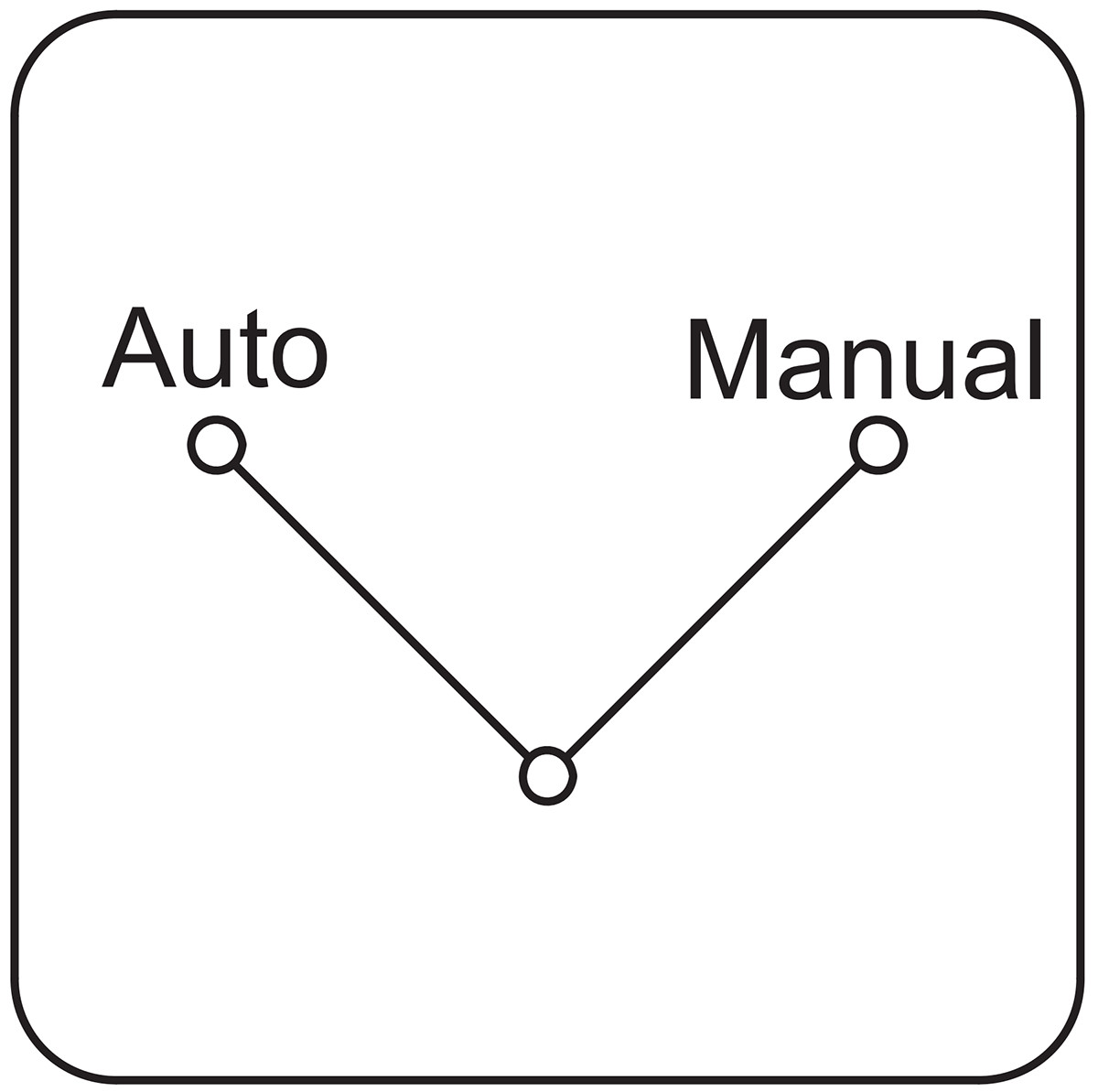 | 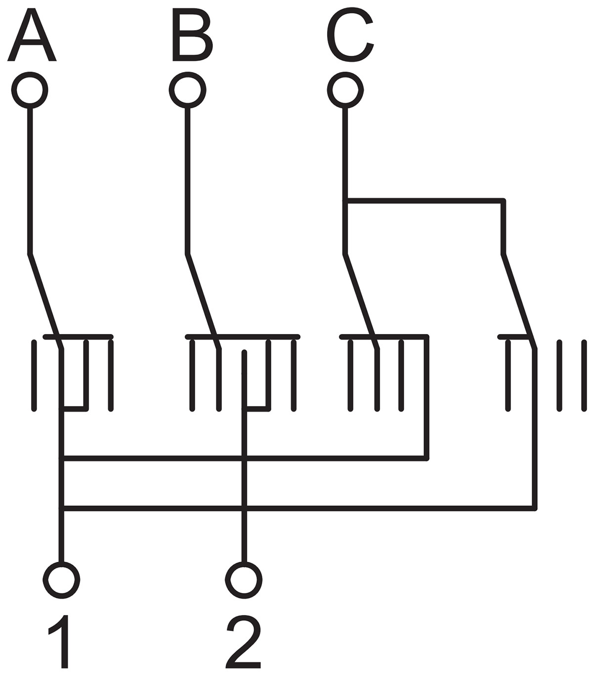 | 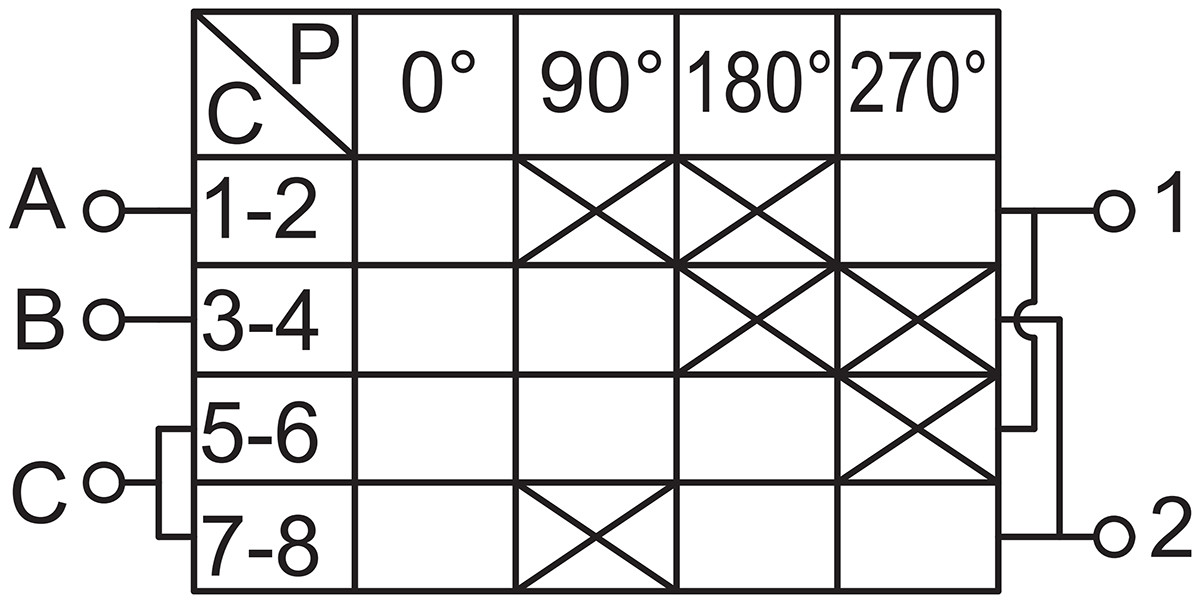 | Dual-button self-resetting normally open pushbutton, left/right operation, etc. |
| W | 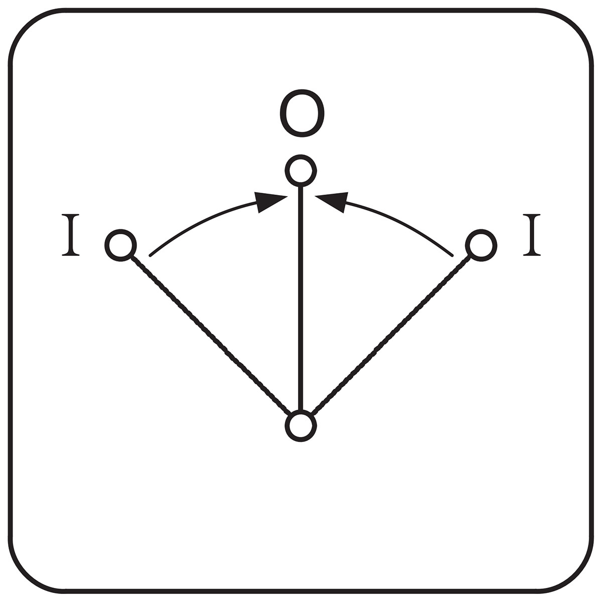 | 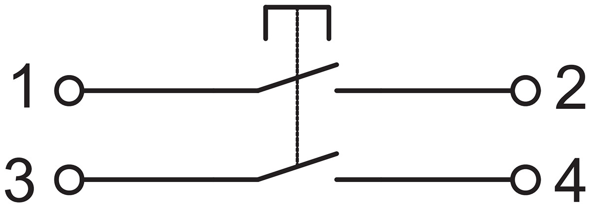 | 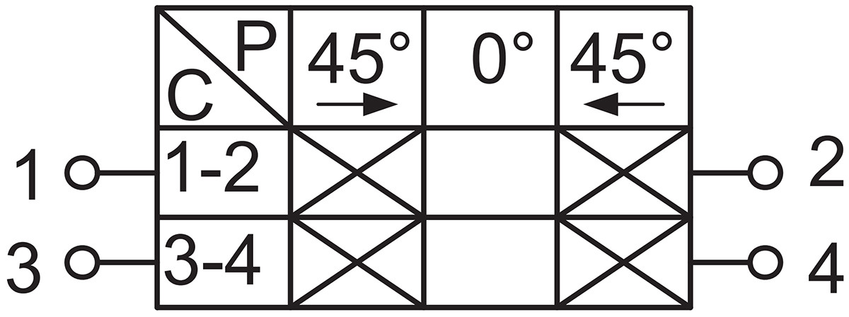 | Dual-button switch |
| X | 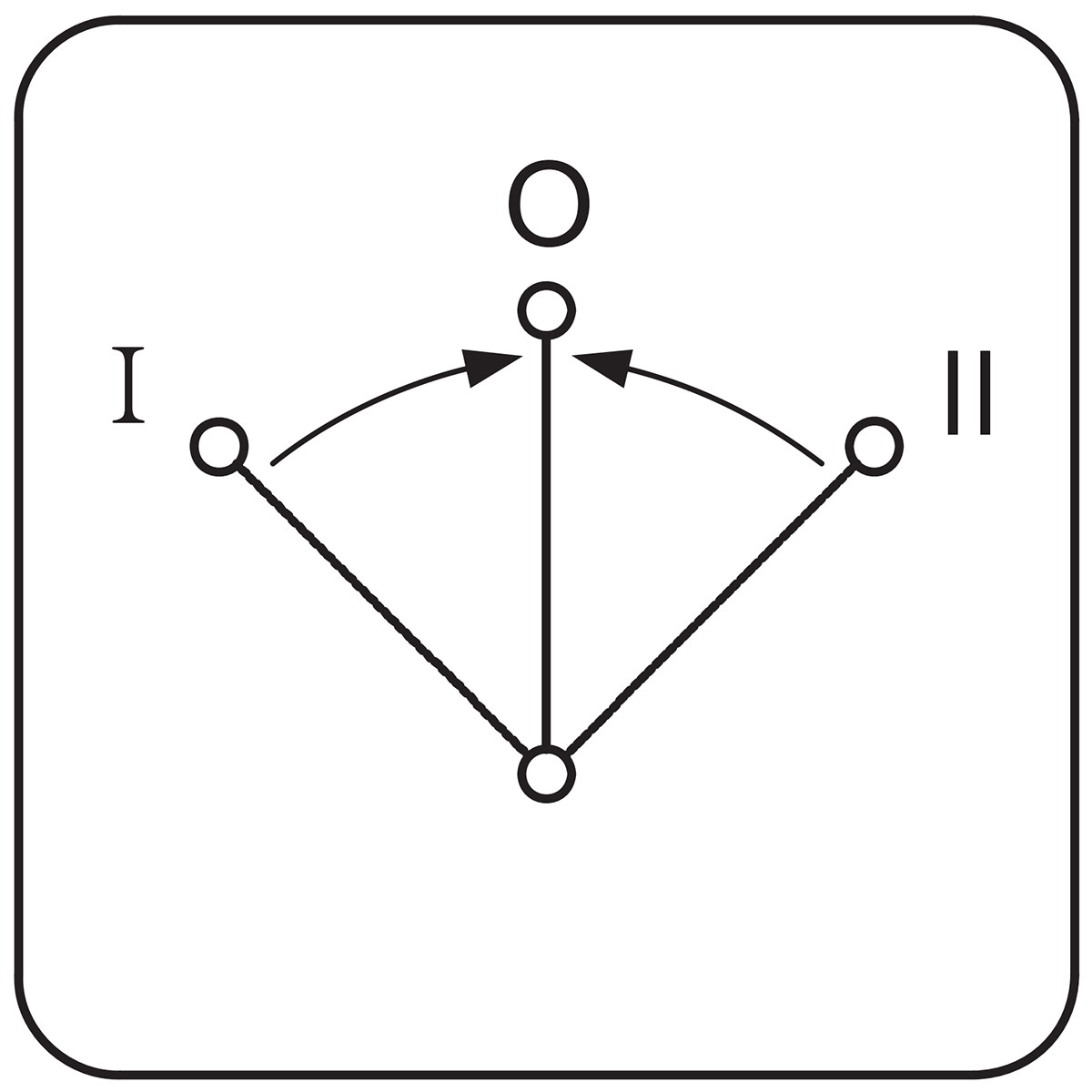 | 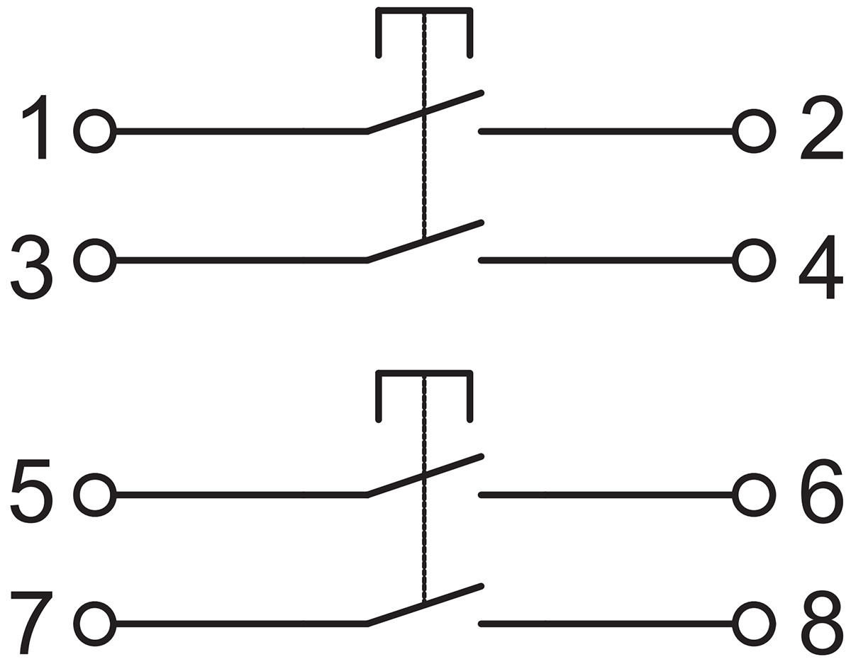 | 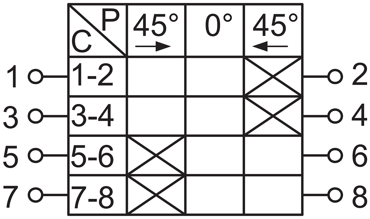 | Three reset buttons, suitable for step-down starters. |
| Y | 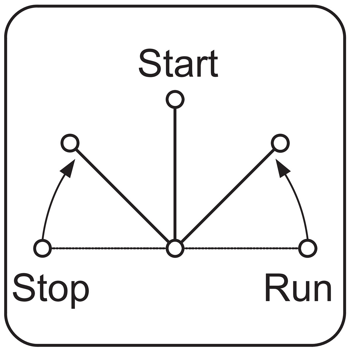 | 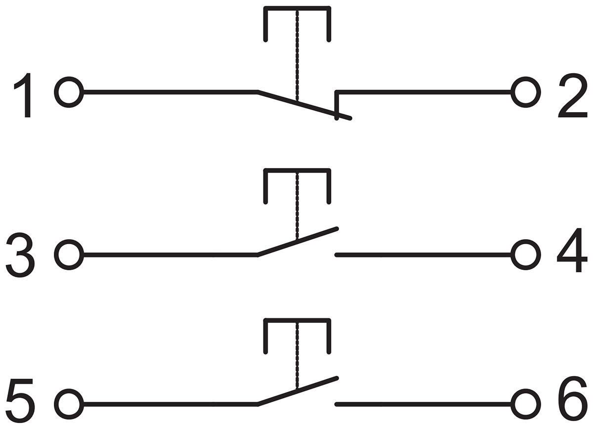 | 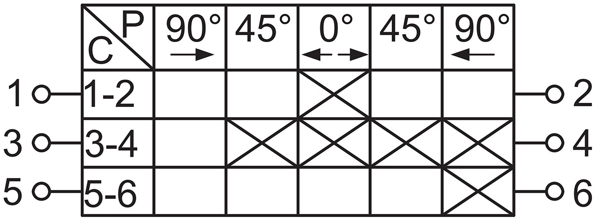 | Power switch, center position open. Left and right positions both closed. Can be used as an explosion-proof fire switch (red). |
| a | 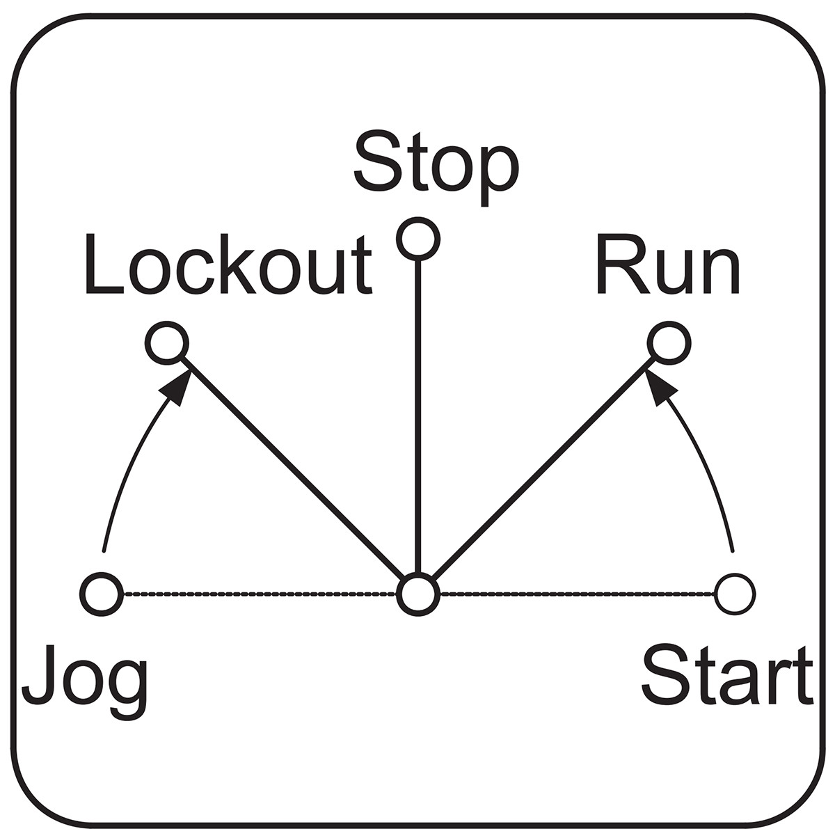 | 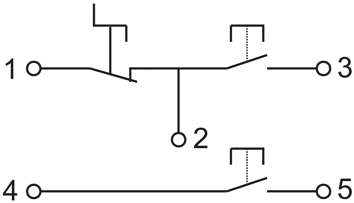 | 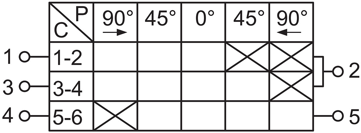 | For starting and jogging hybrid circuits |
| b | 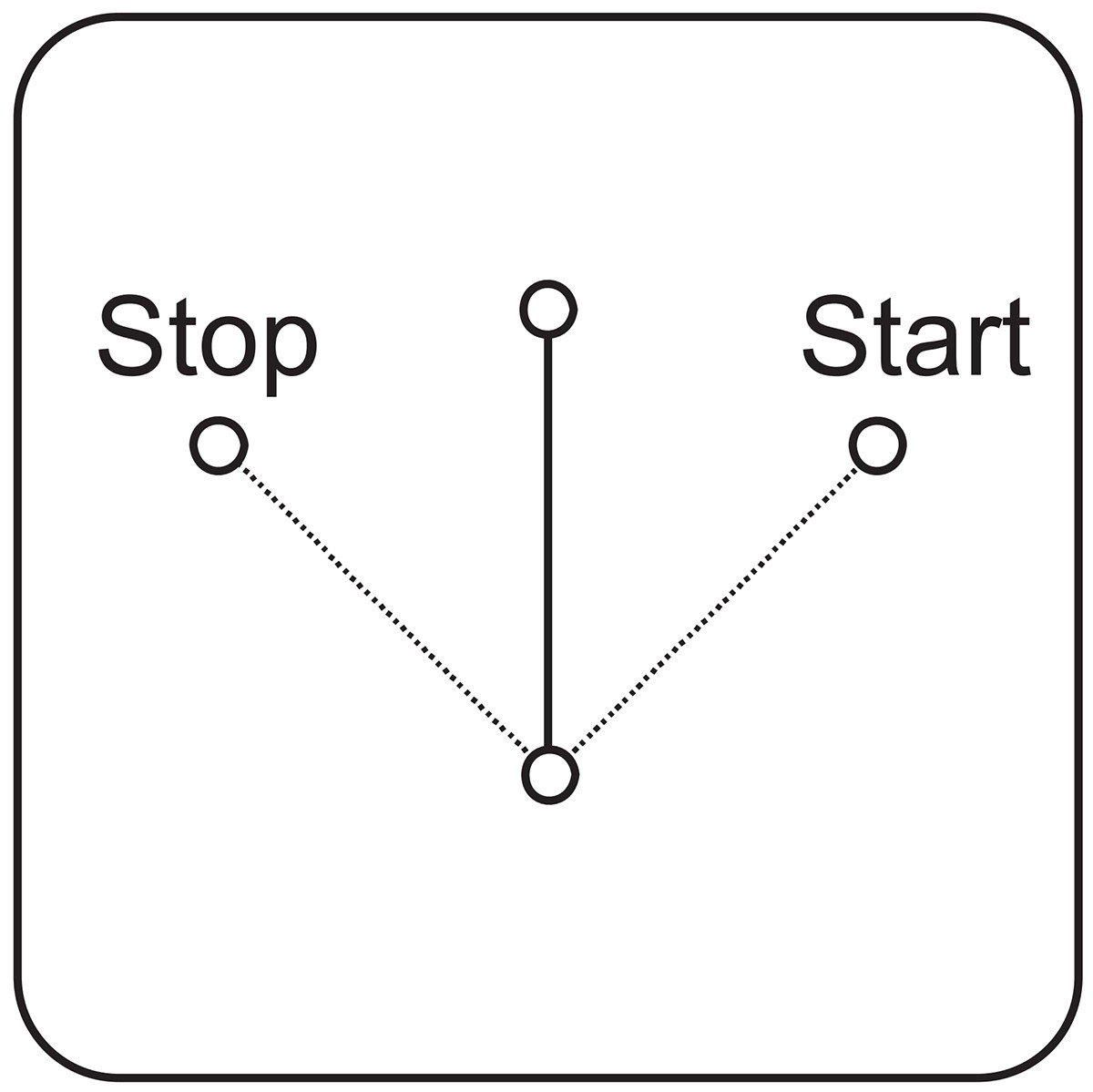 | 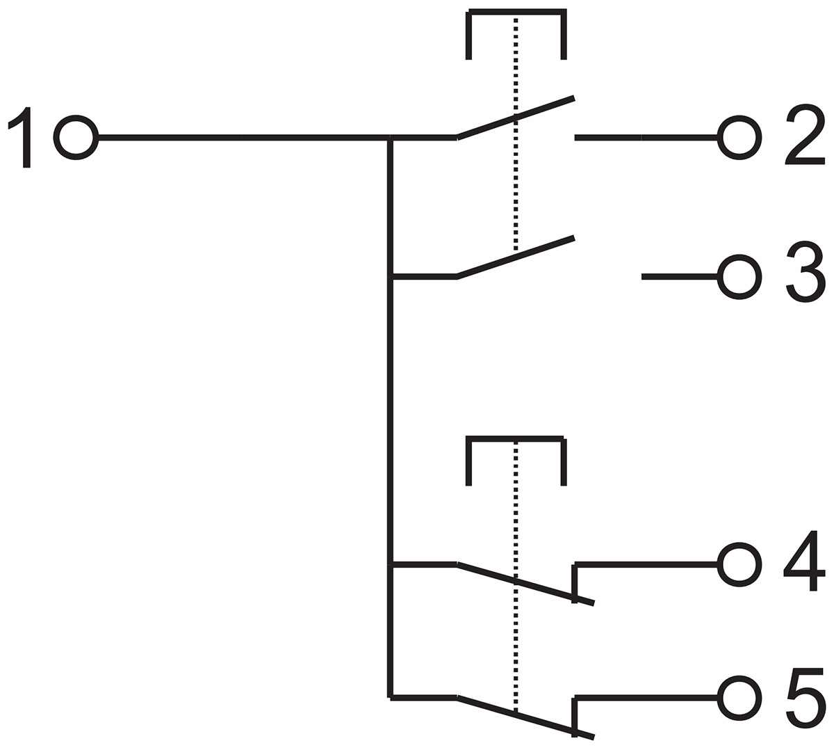 | 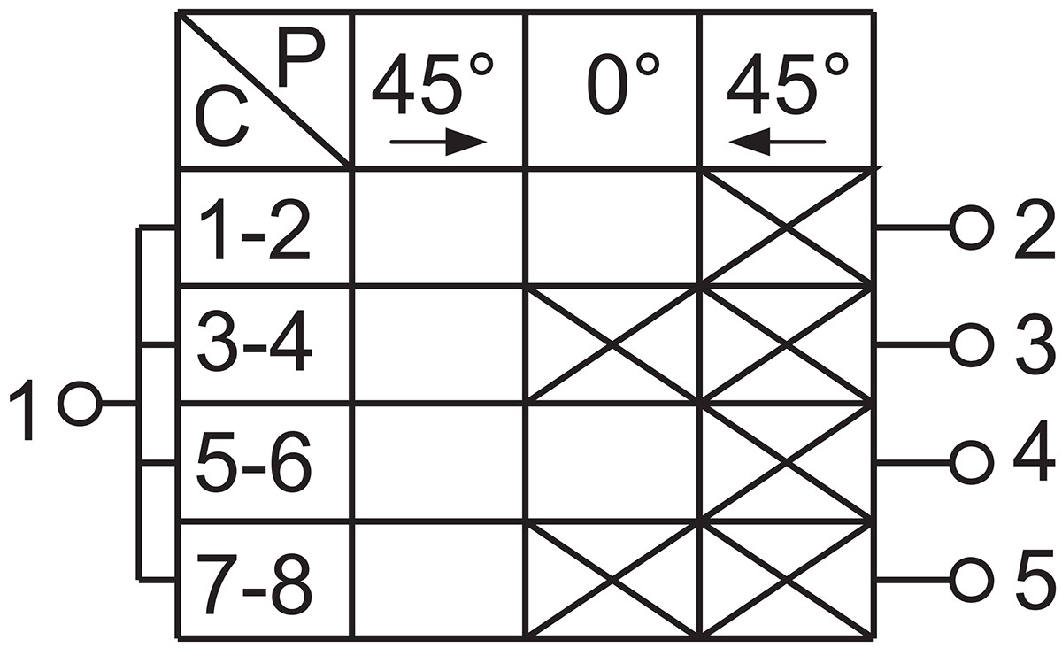 | Double-pole automatic switch |
| c | 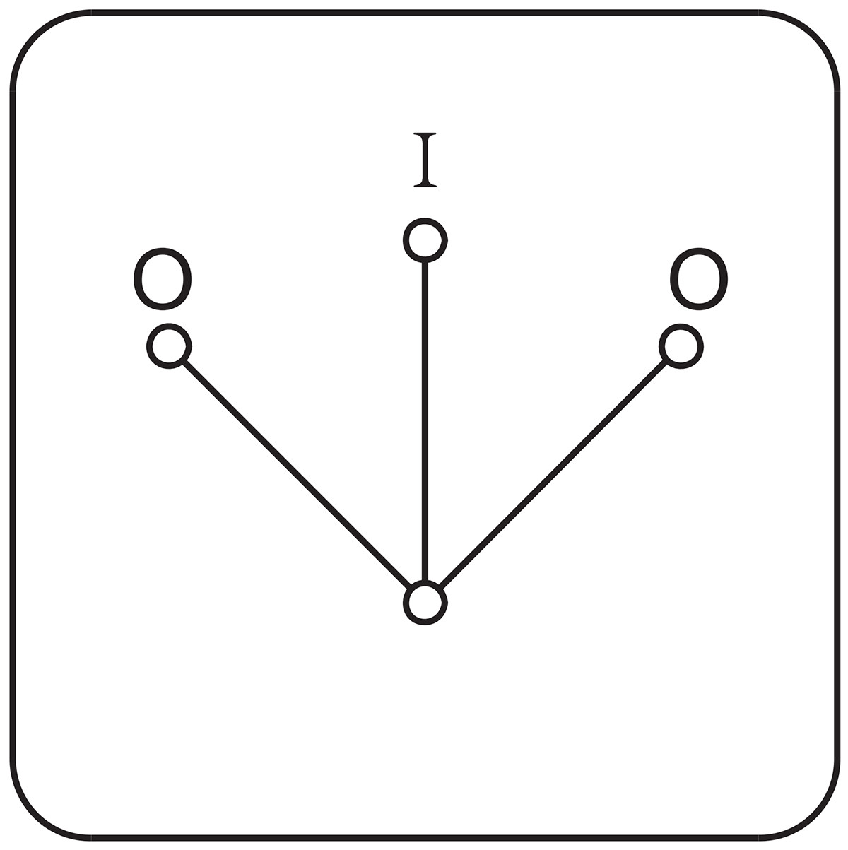 | 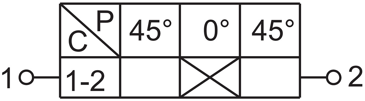 | For emergency stop use; can be disengaged via either left or right operation. Mushroom-head buttons can be provided upon request. | |
| d | | 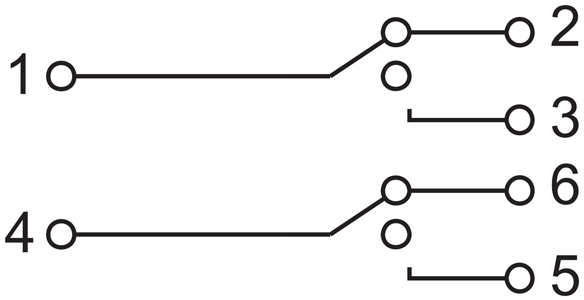 | 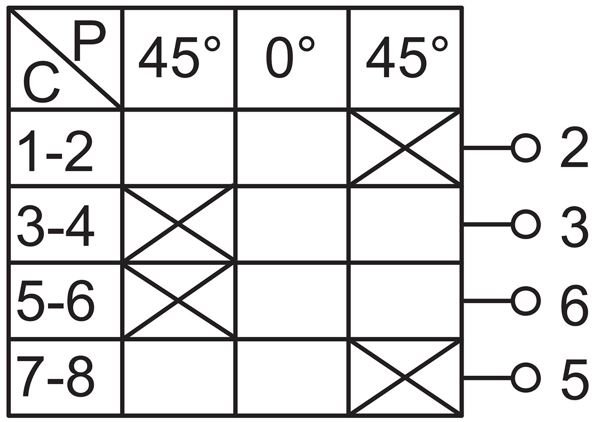 | 2 normally open, 2 normally closed, selector switch |
| e | 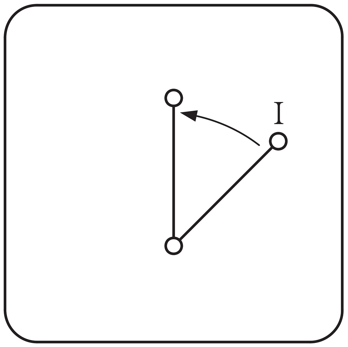 | 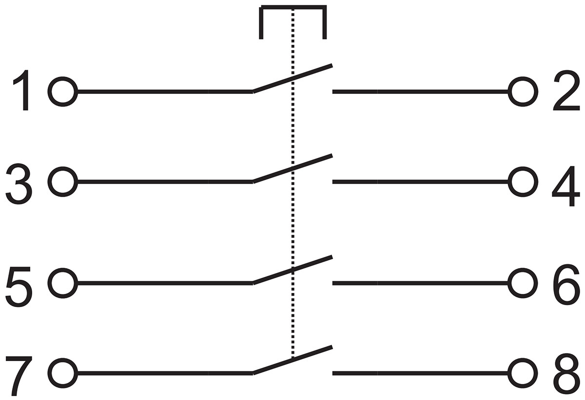 | 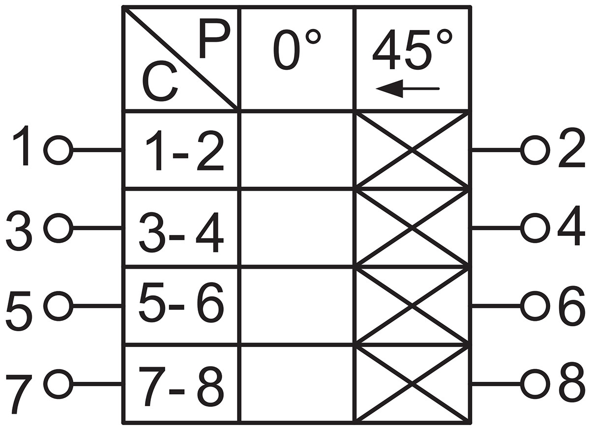 | Self-resetting pushbutton with 4 normally open contacts |
Applicable Scope
1. Suitable for Zone 1 and Zone 2 locations in explosive gas environments;
2. Suitable for Class IIA, IIB, and IIC explosive gas environments;
3. Suitable for Zone 21 and Zone 22 locations in explosive dust environments;
4. Suitable for Class IIIA, IIIB, and IIC explosive dust environments;
5. Suitable for temperature classes T1 to T6;
6. Suitable for hazardous environments in petroleum extraction, refining, chemical processing, power generation, offshore oil platforms, oil tankers, painting, metalworking, and similar applications.